™ ExtremeWireless V2110 Virtual Appliance Installation Guide VMware® Platform 9036509-00 Rev AA Published October 2019
Copyright © 2019 Extreme Networks, Inc. All rights reserved. Legal Notice Extreme Networks, Inc. reserves the right to make changes in specifications and other information contained in this document and its website without prior notice. The reader should in all cases consult representatives of Extreme Networks to determine whether any such changes have been made. The hardware, firmware, software or any specifications described or referred to in this document are subject to change without notice.
Table of Contents Preface................................................................................................................................................................................................ 4 Conventions............................................................................................................................................................................. 4 Documentation and Training...............................................................................
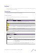
Preface This section discusses the conventions used in this guide, ways to provide feedback, additional help, and other Extreme Networks® publications. Conventions This section discusses the conventions used in this guide. Text Conventions The following tables list text conventions that are used throughout this guide. Table 1: Notice Icons Icon New! Notice Type Alerts you to... General Notice Helpful tips and notices for using the product. Note Important features or instructions.
Documentation and Training To find Extreme Networks product guides, visit our documentation pages at: Current Product Documentation www.extremenetworks.com/documentation/ Archived Documentation (for earlier versions and legacy products) www.extremenetworks.com/support/documentation-archives/ Release Notes www.extremenetworks.com/support/release-notes Hardware/Software Compatibility Matrices https://www.extremenetworks.
Before contacting Extreme Networks for technical support, have the following information ready: • • • • • • • Your Extreme Networks service contract number and/or serial numbers for all involved Extreme Networks products A description of the failure A description of any action(s) already taken to resolve the problem A description of your network environment (such as layout, cable type, other relevant environmental information) Network load at the time of trouble (if known) The device history (for example,
1 V2110 Virtual Appliance Overview This guide describes how to configure and deploy the ExtremeCloud™ Appliance V2110 Virtual Appliance. This guide is a reference for system administrators who install and manage the V2110 Virtual Appliance. Note Any administrator performing tasks described in this guide must have an account with administrative privileges.
2 Deploy the Virtual Appliance V2110 Deployment Requirements V2110 Connectivity Requirements Download a V2110 Image This section provides a requirements overview for the ExtremeCloud™ Appliance Virtual Appliance V2110 deployment. It explains how to install the appliance on a VMware® vSphere™ server (ESXi™) and how to run the initial configuration wizard. V2110 Deployment Requirements V2110 is packaged in the .OVA file format defined by VMware.
Deploy the Virtual Appliance Download a V2110 Image You need a V2110 image file to deploy the virtual machine on your local machine. Download the V2110 software image to your local machine where you manage the vSphere. 1 Access V2110 download page at https://extremeportal.force.com/. 2 Log into the Downloads Home using your Extreme Portal login credentials. 3 Type V2110 in the search tab and click the search icon. The image list is displayed. 4 Download the image from Downloads > Downloads Home tab.
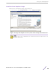
Deploy the Virtual Appliance Install the Virtual Appliance Image Install the V2110 virtual appliance image using the image file. 1 From the vSphere client Getting Stated File menu, select Deploy OVF Template. Figure 2: Deploy OVF Template selection option on the Getting Started File menu Note Even though the V2110 is distributed in the .OVA file format, the menu option refers to the alternate .OVF format.
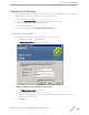
Deploy the Virtual Appliance 2 Select Browse on the Source screen to select the V2110 image, and select Next. The OVF Template Details screen displays information about the selected image file. Figure 3: Deploy OVF Template screen 3 Select Next and verify the OVF template details.
Deploy the Virtual Appliance 4 Enter a name for the V2110 appliance on the Name and Location screen and select Next. Note The name you enter will be used in the vSphere client’s inventory list. It does not have to be the same name as the hostname of the V2110.
Deploy the Virtual Appliance 5 Select Thick provisioned format on the Disk Format screen, and select Next. Note Thick provisioned format allocates storage immediately. Estimated disk usage is 25.0 GB. Figure 6: Disk Format information screen Map the Virtual Appliance Ports to Virtual Networks The Network Mapping dialog is used to map the V2110 ports to virtual networks deployed on the ESX or ESXi host. • The "VM Network" Source Network is the network V2110 management port is expecting to connect to.
Deploy the Virtual Appliance 2 Select the Destination Network for each port by selecting the destination network row in the table. This step opens a drop-down list of virtual switches defined on the host. Figure 7: Network Mapping screen Deploy the Virtual Appliance on the vSphere Client After mapping all the ports to the networks, deploy the virtual appliance on the vSphere client. 1 Select Next on the Network Mapping screen. The Ready to Complete screen displays a summary of your selections.
Deploy the Virtual Appliance 3 Select Finish to complete the deployment. Figure 8: Ready to Complete screen A progress bar reports deployment progress. 4 Select Close when the deployment has completed successfully.
Deploy the Virtual Appliance You are now ready to login and configure the V2110, as described in Virtual Appliance Configuration. Caution After installing the V2110 on a vSphere server, the administrator must not install VMware tools into the virtual machine. This can cause problems for the operating system on the V2110.
3 Configure the Virtual Appliance Access the Virtual Appliance Console Change the Virtual Appliance Management Port IP Address and Appliance Using the CLI Configure V2110 Using the Basic Installation Wizard Set Up the Virtual Appliance to Accept USB Flash Drives Obtain a MAC Address Manually from the vSphere Client After you deploy the virtual appliance on a VMware ESXi server, you are ready to perform initial server configuration. Access the Virtual Appliance Console 1 Log into the vSphere client.
Configure the Virtual Appliance 4 Right-click the virtual appliance on the vSphere Client screen, and select Open Console. Figure 12: Virtual appliance open console option The console will prompt for user credentials. Note Double-click inside the console window to make the window interactive. If the prompt is not visible, select the Enter key. • • For User Name, type admin. For Password, type abc123. You now are working in the V2110 command line interface (CLI).
Configure the Virtual Appliance 6 Apply the ip and appliance command inputs with the apply command: EWC.extremenetworks.com:topology:Admin:l3# apply Configure V2110 Using the Basic Installation Wizard The ExtremeCloud Appliance software provides a Basic Installation Wizard that can help administrators configure the minimum settings necessary to deploy a fully functioning V2110 appliance on a network.
Configure the Virtual Appliance 5 In the vSphere client, right-click the name of the virtual appliance from the list of guest operating systems, select Edit Settings. Figure 13: Edit Settings options in the vSphere client for adding USB flash drives 6 Select Add in the Virtual Properties dialog. The Add Hardware dialog box appears. If running vSphere 4.1 or later and a USB device has been inserted and is not assigned to another guest, the USB Device option will be listed.
Configure the Virtual Appliance 7 Select the USB Device option, and select Next. The Select USB device dialog appears. The dialog lists all USB devices plugged into the host that are not assigned to guest operating systems. 8 Select a USB Flash drive (as other devices are not supported by V2110), and select Next. Figure 15: USB flash drive selection The Ready to Complete dialog appears. 9 Review the settings and then select Finish to add the USB device to V2110 or select Cancel to abort the operation.
Configure the Virtual Appliance 10 Select Ok to save the configuration. 11 Open the V2110 Virtual Machine Properties dialog on the main vSphere Client screen and select the Hardware tab. The USB device will be listed under Hardware. You can now use the USB flash drive on V2110 just as you would on a physical controller. Manage the Flash Memory 1 Right-click the name of the appliance, and select Power. 2 From the Power menu, select Power On. 3 From the Wireless Assistant menu, select Wireless Controller.
Configure the Virtual Appliance 4 From the left-pane, select Administration, then select Flash. The Flash Memory Configuration page is displayed. Figure 17: Flash Memory Confuguration page Remove the Flash Drive 1 When you are ready to remove the USB flash drive, select Un-Mount from the Flash Memory dialog. 2 Remove the flash drive. You can delete the USB flash drive from the Virtual Machine Properties dialog after unmounting it.
Configure the Virtual Appliance 2 Install the Virtual Appliance ova file. For more information, see Deploy the Virtual Appliance. 3 Shut down the V2110 as described in the following steps: 1 In the vSphere Client screen, right-click V2110. 2 Select Power. 3 From the Power sub-menu, select Shut Down Guest. Caution Do not select Power Off as this will terminate the connection to V2110. 4 Right-click the virtual appliance from the list of guest operating systems on the vSphere client screen.
Configure the Virtual Appliance 8 Power on the V2110 from the vSphere client. 9 From the Wireless Assistant menu, select Wireless Controller. 10 Select Administration > Software Maintenance > HWC Product Keys. The license summary is displayed. 11 Verify that the locking ID matches the manually assigned MAC address. Figure 20: License Summary section 12 Redeem virtual appliance licenses, such as the Regulatory Domain key, using this MAC address.
4 Configure vSwitches for the Virtual Appliance Create a New Virtual Switch on the ESXi Server Configure the Virtual Switch for Promiscuous Connections Configure the Virtual Switch for Jumbo Frames Support The Virtual Appliance has some specific requirements on the virtual switches (vSwitches) to which its data plane ports (esa0, esa1) are connected. This section explains how to create a vSwitch on an ESX or ESXi 4.1 U1 host that satisfies these requirements.
Configure vSwitches for the Virtual Appliance 5 Set the following using the wizard: • • • Set the connection type to Virtual Machine. Assign a physical NIC Name to the switch. Assign a VLAN ID. Important Select “All (4095)” for the VLAN ID. This setting enables VLAN trunking to virtual guest operating systems using the virtual switch. The VLAN ID can be changed later using the Virtual Switch property dialog.
Configure vSwitches for the Virtual Appliance 2 On the vSphere Client Configuration screen, select the Properties link next to the virtual switch to be configured. The vSwitch Properties screen is displayed. Figure 22: vSwitch properties screen 3 Select Ports tab on the vSwitch Properties window.
Configure vSwitches for the Virtual Appliance 4 From the Ports list, double-click the vSwitch entry. The vSwitch Properties dialog displays. Figure 23: vSwitch properties information screen 5 Select the Security tab on the vSwitch Properties window.
Configure vSwitches for the Virtual Appliance 6 Set all Policy Exceptions to Accept on the Security screen. Figure 24: Policy exceptions selection screen 7 Select Ok. 8 On the vSwitch Properties dialog, double-click the name of the port group that will be used by V2110 data plane port. 9 On the Port Group Properties dialog, select the General tab, and set the VLANID (Optional) field to All (4095).
Configure vSwitches for the Virtual Appliance 10 Select Ok. This causes the vSwitch and port group to trunk any VLANs received on its NICs to V2110 with the VLAN tag intact. Figure 25: Port group properties selection screen 11 Select the Security tab on the Wireless Domain Properties window, and set all options to Accept. 12 Select Ok twice to close the vSwitch properties dialog.
Configure vSwitches for the Virtual Appliance For information on how to enable Jumbo Frames support on your controller, refer to the ExtremeWireless User Guide. To configure the vSwitch for Jumbo Frames support: 1 Log into the vSphere client host network. 2 On the vSphere Client Configuration screen, select the Properties link next to the virtual switch to be configured. The vSwitch Properties screen is displayed. Figure 26: vSwitch properties screen 3 Select Ports tab on the vSwitch Properties window.
Configure vSwitches for the Virtual Appliance 4 From the Ports list, double-click the vSwitch entry. The vSwitch Properties dialog displays. Figure 27: vSwitch properties MTU information screen 5 6 7 8 On the vSwitch Properties dialog, select the General tab. In the Advanced Properties section, set the MTU to 1800. Select Ok. Select Close to close the vSwitch Properties dialog window.
Index A access the virtual appliance console 17 B basic installation wizard V2110 configuration 19 C change the port IP address 18 configure 17 conventions notice icons 4 text 4 create a new virtual switch 26 D documentation feedback 5 location 5 F flash memory management 22 download the v2110 image (continued) connectivity requirements 8 deployment requirements 8 download the v2110 image install and deploy the virtual appliance image 8 log into the vSphere client 8 v2110 deployment on vSphere client 1