
Installation Guide


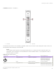


Table Of Contents
- ExtremeRouting SLX 9850-4 Hardware Installation Guide
- Preface
- About this Document
- Device Overview
- Preparing for the Installation
- Mounting the Device
- Initial Setup and Verification
- Initial setup and configuration checklist
- Items required
- Providing power to the device
- Establishing a serial connection
- Configuring a static IP address
- Establishing an Ethernet connection
- Customizing the chassis and host names
- Configuring the DNS service
- Setting the date and time
- Verifying correct operation
- Backing up the configuration
- Powering down the device
- Installing cable management kit
- Monitoring the Device
- Management Modules
- Interface Modules
- Power Supply Modules
- Power supply module overview
- Precautions specific to the power supply module
- Time and items required for removal and replacement
- Removing an AC power supply module
- Inserting an AC power supply module
- Removing a DC power supply module
- Inserting a DC power supply module
- Verifying power supply module operation
- High Voltage Power Supply Unit supporting AC and DC Voltages
- Fan Modules
- Switch Fabric Modules
- Transceivers and cables
- Supported transceivers and cables
- Time and items required
- Precautions specific to transceivers and cables
- Cleaning the fiber-optic connectors
- Managing cables
- Installing an SFP+ transceiver
- Replacing an SFP+ transceiver
- Installing a QSFP28 transceiver
- Replacing a QSFP28 transceiver
- Breakout cables
- Verifying transceiver operation
- Hardware Maintenance Schedule
- ExtremeRouting SLX 9850 Technical Specifications
- System specifications
- Ethernet
- LEDs
- Other
- Weight and physical dimensions
- Environmental requirements
- Power supply specifications (per PSU)
- Power consumption (typical configuration)
- Power consumption (maximum configuration)
- Power consumption (modules) (typical configuration)
- Power consumption (modules) (maximum configuration)
- Data port specifications (Ethernet)
- Serial port specifications (pinout RJ-45)
- Serial port specifications (protocol)
- Memory specifications
- Regulatory compliance (EMC)
- Regulatory compliance (safety)
- Regulatory compliance (environmental)
- Regulatory Statements
- Cautions and Danger Notices

FIGURE 38 DC power supply LEDs
1. LED 1 - DC in good 2. LED 2 - DC out good
TABLE 21 PS module LED
descriptions
LED purpose Color Status Recommended action
Power supply module status LED 1 and LED 2: Steady green Input and output voltages are within
range
No action is required.
LED 1: O
LED 2: Flashing yellow
Power supply does not have incoming
power and is not providing power to
the device, or the Input AC voltage is
out of range.
Ensure that the power supply is
rmly seated, the power cable is
connected, and that the power
cable is connected to a power
source.
Disconnect the power cable from
the power supply, remove and
reinsert the power supply, and
then reconnect the power cable
to restart.
If this condition persists, replace
the power supply assembly.
LED 1: Green
LED 2: Yellow
Output voltage is out of range If this condition persists, replace
the power supply assembly.
LED 1: Green
LED 2: Flashing Yellow/Green
Over-temperature warning or fan error Check the fan.
Interpreting power supply module LEDs
ExtremeRouting SLX 9850-4 Hardware Installation Guide
82 9035331-02