
Installation Guide

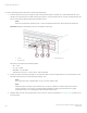


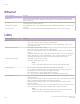
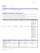
Table Of Contents
- ExtremeRouting SLX 9850-4 Hardware Installation Guide
- Preface
- About this Document
- Device Overview
- Preparing for the Installation
- Mounting the Device
- Initial Setup and Verification
- Initial setup and configuration checklist
- Items required
- Providing power to the device
- Establishing a serial connection
- Configuring a static IP address
- Establishing an Ethernet connection
- Customizing the chassis and host names
- Configuring the DNS service
- Setting the date and time
- Verifying correct operation
- Backing up the configuration
- Powering down the device
- Installing cable management kit
- Monitoring the Device
- Management Modules
- Interface Modules
- Power Supply Modules
- Power supply module overview
- Precautions specific to the power supply module
- Time and items required for removal and replacement
- Removing an AC power supply module
- Inserting an AC power supply module
- Removing a DC power supply module
- Inserting a DC power supply module
- Verifying power supply module operation
- High Voltage Power Supply Unit supporting AC and DC Voltages
- Fan Modules
- Switch Fabric Modules
- Transceivers and cables
- Supported transceivers and cables
- Time and items required
- Precautions specific to transceivers and cables
- Cleaning the fiber-optic connectors
- Managing cables
- Installing an SFP+ transceiver
- Replacing an SFP+ transceiver
- Installing a QSFP28 transceiver
- Replacing a QSFP28 transceiver
- Breakout cables
- Verifying transceiver operation
- Hardware Maintenance Schedule
- ExtremeRouting SLX 9850 Technical Specifications
- System specifications
- Ethernet
- LEDs
- Other
- Weight and physical dimensions
- Environmental requirements
- Power supply specifications (per PSU)
- Power consumption (typical configuration)
- Power consumption (maximum configuration)
- Power consumption (modules) (typical configuration)
- Power consumption (modules) (maximum configuration)
- Data port specifications (Ethernet)
- Serial port specifications (pinout RJ-45)
- Serial port specifications (protocol)
- Memory specifications
- Regulatory compliance (EMC)
- Regulatory compliance (safety)
- Regulatory compliance (environmental)
- Regulatory Statements
- Cautions and Danger Notices

4. Position a cable so that the key (the ridge on one side of the cable connector) is aligned with the slot in the transceiver. Insert the
cable into the transceiver until the latching mechanism clicks.
NOTE
If your transceiver has an integrated cable attached, you will not install a cable.
When both ends of the cable are inserted and the link is fully established, the LED displays steady green.
NOTE
Cables are keyed so that they can be inserted in only one way. If a cable does not slide in easily, ensure that it is
correctly oriented.
5. Organize cables to avoid covering LEDs and air vents. Refer to Managing cables on page 127 for more information.
Breakout cables
The 36-port 100GbE, 60-port 40GbE, or 240-port 10GbE
ex-speed interface module supports 240 10GbE ports per module by
using QSFP to 4 SFP+ 40GbE-to-10GbE copper breakout cables, or 40G-QSFP-SR4-INT and 40G-QSFP-ESR4 optics for use with
ber breakout cables. The copper breakout cables are terminated with optical connectors and are available in 1m, 3m, 5m, and greater
lengths. No additional connectors or cabling are required when using the copper breakout. When using the ber breakout cables,
additional 10Gb optics are required.
FIGURE 68 QSFP+ to 4 SFP+ (4 x 10 GbE) direct-attach copper breakout cable
Verifying transceiver operation
To verify operation of a transceiver, view the LEDs on the transceiver. To
nd the LED locations on the interface modules, refer to
Interpreting interface module LEDs on page 77 . After you have connected and congured the ports for Ethernet connectivity and
connected the cable to another active port, the LED becomes solid green. When trac is detected on the port, the light becomes blinking
green.
You can also enter the show interface status and show ip interface brief commands to verify proper transceiver operation.
Breakout cables
ExtremeRouting SLX 9850-4 Hardware Installation Guide
134 9035331-02