
Installation Guide


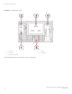

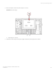
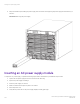
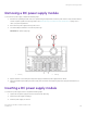
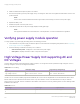
Table Of Contents
- ExtremeRouting SLX 9850-4 Hardware Installation Guide
- Preface
- About this Document
- Device Overview
- Preparing for the Installation
- Mounting the Device
- Initial Setup and Verification
- Initial setup and configuration checklist
- Items required
- Providing power to the device
- Establishing a serial connection
- Configuring a static IP address
- Establishing an Ethernet connection
- Customizing the chassis and host names
- Configuring the DNS service
- Setting the date and time
- Verifying correct operation
- Backing up the configuration
- Powering down the device
- Installing cable management kit
- Monitoring the Device
- Management Modules
- Interface Modules
- Power Supply Modules
- Power supply module overview
- Precautions specific to the power supply module
- Time and items required for removal and replacement
- Removing an AC power supply module
- Inserting an AC power supply module
- Removing a DC power supply module
- Inserting a DC power supply module
- Verifying power supply module operation
- High Voltage Power Supply Unit supporting AC and DC Voltages
- Fan Modules
- Switch Fabric Modules
- Transceivers and cables
- Supported transceivers and cables
- Time and items required
- Precautions specific to transceivers and cables
- Cleaning the fiber-optic connectors
- Managing cables
- Installing an SFP+ transceiver
- Replacing an SFP+ transceiver
- Installing a QSFP28 transceiver
- Replacing a QSFP28 transceiver
- Breakout cables
- Verifying transceiver operation
- Hardware Maintenance Schedule
- ExtremeRouting SLX 9850 Technical Specifications
- System specifications
- Ethernet
- LEDs
- Other
- Weight and physical dimensions
- Environmental requirements
- Power supply specifications (per PSU)
- Power consumption (typical configuration)
- Power consumption (maximum configuration)
- Power consumption (modules) (typical configuration)
- Power consumption (modules) (maximum configuration)
- Data port specifications (Ethernet)
- Serial port specifications (pinout RJ-45)
- Serial port specifications (protocol)
- Memory specifications
- Regulatory compliance (EMC)
- Regulatory compliance (safety)
- Regulatory compliance (environmental)
- Regulatory Statements
- Cautions and Danger Notices

4. Make sure that the latch snaps into place in the chassis.
5. Reconnect the power lugs to the power supply unit by connecting the -48V wire to the negative terminal and the 0V wire to the
positive terminal.
NOTE
The DC return must be isolated from the device ground (DC-I) when making connections to the power supply.
6. Replace the safety cover.
7. Reattach the power cord to the power source.
8. Verify that the power LED on the power supply displays a steady green light.
NOTE
This equipment installation must meet NEC/CEC code requirements. Consult local authorities for regulations.
Verifying power supply module operation
To verify operation of a power supply assembly, perform the following procedure.
1. Check the LEDs on the power supply module front panel. For information about interpreting LED patterns, refer to Interpreting
power supply module LEDs on page 80.
2. Enter the following commands and note any error conditions:
• show environment power - Displays the current status of the power supply.
• show system - Displays information of each component in the system.
High Voltage Power Supply Unit supporting AC and
DC Voltages
The SLX 9850-4 supports High Voltage Power Supply Unit (PSU). It is a single PSU that can operate both High Voltage AC (HV AC)
and High Voltage DC (HV DC) in the ranges shown below:
TABLE 24 HV PSU Rating
Type Rated Input Voltage Supported Input Voltage Range
High Voltage DC (HVDC) 240V - 380VDC 192V-400VDC
High Voltage AC (HVAC) 100V - 120VAC, 200V - 277VAC 90V - 132VAC, 180-305VAC
Similar to the AC PSU that is already supported and released, the HV PSU have an integrated fan in it and therefore will need to match
airow of the PSU fan to the base chassis airow. There is only one air direction version and it will intake air from the port side and
exhaust to the non-port side. This PSU is oered to match airow of the chassis. In summary, following are two HV PSU oerings made
available for SLX 9850-4 .
TABLE 25
HV PSU
Input Voltage Air-ow Type Input Connector
HV DC, 240V-380V DC
&
Intake - NPI SAF-D Type
Verifying power supply module operation
ExtremeRouting SLX 9850-4 Hardware Installation Guide
110 9035331-02