
Installation Guide
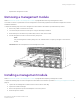
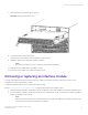
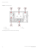
Table Of Contents
- ExtremeRouting SLX 9850-8 Hardware Installation Guide
- Preface
- About this Document
- Device Overview
- Preparing for the Installation
- Mounting the Device
- Initial Setup and Verification
- Initial setup and configuration checklist
- Items required
- Providing power to the device
- Establishing a serial connection
- Configuring a static IP address
- Establishing an Ethernet connection
- Customizing the chassis and host names
- Configuring the DNS service
- Setting the date and time
- Verifying correct operation
- Backing up the configuration
- Powering down the device
- Installing cable management kit
- Monitoring the Device
- Management Modules
- Interface Modules
- Power Supply Modules
- Power supply module overview
- Precautions specific to the power supply module
- Time and items required for removal and replacement
- Removing an AC power supply module
- Inserting an AC power supply module
- Removing a DC power supply module
- Inserting a DC power supply module
- Verifying power supply module operation
- High Voltage Power Supply Unit supporting AC and DC Voltages
- Fan Modules
- Switch Fabric Modules
- Transceivers and cables
- Supported transceivers and cables
- Time and items required
- Precautions specific to transceivers and cables
- Cleaning the fiber-optic connectors
- Managing cables
- Installing an SFP+ transceiver
- Replacing an SFP+ transceiver
- Installing a QSFP28 transceiver
- Replacing a QSFP28 transceiver
- Breakout cables
- Verifying transceiver operation
- Hardware Maintenance Schedule
- ExtremeRouting SLX 9850 Technical Specifications
- System specifications
- Ethernet
- LEDs
- Other
- Weight and physical dimensions
- Environmental requirements
- Power supply specifications (per PSU)
- Power consumption (typical configuration)
- Power consumption (maximum configuration)
- Power consumption (modules) (typical configuration)
- Power consumption (modules) (maximum configuration)
- Data port specifications (Ethernet)
- Serial port specifications (pinout RJ-45)
- Serial port specifications (protocol)
- Memory specifications
- Regulatory compliance (EMC)
- Regulatory compliance (safety)
- Regulatory compliance (environmental)
- Regulatory Statements
- Cautions and Danger Notices

7. Slide the interface module all the way into the slot.
FIGURE 50 Inserting an interface module
8. Close the ejectors by rotating them inward.
The levering action of the ejectors seats the interface module in the slot.
9. Tighten the captive screws using the #2 Phillips screwdriver.
NOTE
The interface module will not function unless the captive screws are tightened.
10. Install the transceivers and cables in the interface module.
11. Group and route the cables using a cable management comb.
Removing or replacing an interface module
This section describes the physical procedure for removing or replacing an interface module in chassis slots. It does not cover
management modules or switch fabric modules.
Complete the following steps to remove or replace an interface module.
Review Precautions
specic to the interface modules on page 95 before replacing an interface module.
1. Check for adequate cable slack. Ensure there is plenty of cable slack to remove an interface module without cable obstruction.
2. If you are replacing an interface module of the same type, ensure that the part number on the interface module being replaced
matches the replacement part number.
NOTE
Before removing any cables from an interface module, note the cable order (identify each cable by its physical port). It
is a good practice to keep a table of cable to port mapping.
Removing or replacing an interface module
ExtremeRouting SLX 9850-8 Hardware Installation Guide
9035475-02 Rev AA 97