
Installation Guide
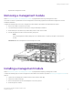
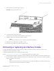
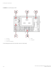
Table Of Contents
- ExtremeRouting SLX 9850-8 Hardware Installation Guide
- Preface
- About this Document
- Device Overview
- Preparing for the Installation
- Mounting the Device
- Initial Setup and Verification
- Initial setup and configuration checklist
- Items required
- Providing power to the device
- Establishing a serial connection
- Configuring a static IP address
- Establishing an Ethernet connection
- Customizing the chassis and host names
- Configuring the DNS service
- Setting the date and time
- Verifying correct operation
- Backing up the configuration
- Powering down the device
- Installing cable management kit
- Monitoring the Device
- Management Modules
- Interface Modules
- Power Supply Modules
- Power supply module overview
- Precautions specific to the power supply module
- Time and items required for removal and replacement
- Removing an AC power supply module
- Inserting an AC power supply module
- Removing a DC power supply module
- Inserting a DC power supply module
- Verifying power supply module operation
- High Voltage Power Supply Unit supporting AC and DC Voltages
- Fan Modules
- Switch Fabric Modules
- Transceivers and cables
- Supported transceivers and cables
- Time and items required
- Precautions specific to transceivers and cables
- Cleaning the fiber-optic connectors
- Managing cables
- Installing an SFP+ transceiver
- Replacing an SFP+ transceiver
- Installing a QSFP28 transceiver
- Replacing a QSFP28 transceiver
- Breakout cables
- Verifying transceiver operation
- Hardware Maintenance Schedule
- ExtremeRouting SLX 9850 Technical Specifications
- System specifications
- Ethernet
- LEDs
- Other
- Weight and physical dimensions
- Environmental requirements
- Power supply specifications (per PSU)
- Power consumption (typical configuration)
- Power consumption (maximum configuration)
- Power consumption (modules) (typical configuration)
- Power consumption (modules) (maximum configuration)
- Data port specifications (Ethernet)
- Serial port specifications (pinout RJ-45)
- Serial port specifications (protocol)
- Memory specifications
- Regulatory compliance (EMC)
- Regulatory compliance (safety)
- Regulatory compliance (environmental)
- Regulatory Statements
- Cautions and Danger Notices

• Replacement management module
Removing a management module
Refer to Precautions specic to the management modules on page 88 before removing a management module.
The chassis continues to operate while an active management module is being replaced if the redundant management module is
installed and initialized.
Complete the following steps to remove a management module. Refer to the illustration provided with the procedure.
1. Remove any cables connected to the module.
2. Unscrew the captive screws from both ejectors using the #2 Phillips screwdriver.
3. Rotate both ejectors simultaneously outward, away from the center of the module.
4. Pull the management module out of the chassis by the ejectors.
NOTE
Carry the management module by lifting it from its underside, and do not place your ngers in the side of the
module.
FIGURE 44 Removal and replacement of the management module
Installing a management module
Refer to Precautions specic to the management modules on page 88 before replacing a management module.
Complete the following steps to insert a management module. Refer to the illustration provided in Removing a management module on
page 91.
1. Unpack the new management module and remove it from the anti-static bag.
2. Inspect the module for damage.
3. Remove the protective caps from the backplane connectors, if present.
4. Rotate the ejectors outward.
Installing a management module
ExtremeRouting SLX 9850-8 Hardware Installation Guide
9035475-02 Rev AA 91