
Installation Guide
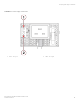
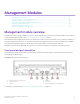
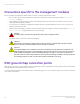
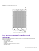
Table Of Contents
- ExtremeRouting SLX 9850-8 Hardware Installation Guide
- Preface
- About this Document
- Device Overview
- Preparing for the Installation
- Mounting the Device
- Initial Setup and Verification
- Initial setup and configuration checklist
- Items required
- Providing power to the device
- Establishing a serial connection
- Configuring a static IP address
- Establishing an Ethernet connection
- Customizing the chassis and host names
- Configuring the DNS service
- Setting the date and time
- Verifying correct operation
- Backing up the configuration
- Powering down the device
- Installing cable management kit
- Monitoring the Device
- Management Modules
- Interface Modules
- Power Supply Modules
- Power supply module overview
- Precautions specific to the power supply module
- Time and items required for removal and replacement
- Removing an AC power supply module
- Inserting an AC power supply module
- Removing a DC power supply module
- Inserting a DC power supply module
- Verifying power supply module operation
- High Voltage Power Supply Unit supporting AC and DC Voltages
- Fan Modules
- Switch Fabric Modules
- Transceivers and cables
- Supported transceivers and cables
- Time and items required
- Precautions specific to transceivers and cables
- Cleaning the fiber-optic connectors
- Managing cables
- Installing an SFP+ transceiver
- Replacing an SFP+ transceiver
- Installing a QSFP28 transceiver
- Replacing a QSFP28 transceiver
- Breakout cables
- Verifying transceiver operation
- Hardware Maintenance Schedule
- ExtremeRouting SLX 9850 Technical Specifications
- System specifications
- Ethernet
- LEDs
- Other
- Weight and physical dimensions
- Environmental requirements
- Power supply specifications (per PSU)
- Power consumption (typical configuration)
- Power consumption (maximum configuration)
- Power consumption (modules) (typical configuration)
- Power consumption (modules) (maximum configuration)
- Data port specifications (Ethernet)
- Serial port specifications (pinout RJ-45)
- Serial port specifications (protocol)
- Memory specifications
- Regulatory compliance (EMC)
- Regulatory compliance (safety)
- Regulatory compliance (environmental)
- Regulatory Statements
- Cautions and Danger Notices

Precautions specic to the management modules
Be sure to perform the following procedures before you remove or replace a management module.
• Be sure to back up the conguration before you replace the management module by following the steps in Backing up the
conguration on page 73.
• The management module is sensitive to electrostatic discharge (ESD). When working with any Extreme module, use correct
electrostatic discharge (ESD) procedures.
• Any slot that is not occupied by a management module should be occupied by a ller panel to ensure correct cooling of the
chassis and protection from dust.
• Wear a wrist grounding strap connected to chassis ground (if the device is plugged in) or a bench ground. Refer to ESD ground
strap connection points on page 88 for the location of the ESD jack.
DANGER
For safety reasons, the ESD wrist strap should contain a series 1 megaohm resistor.
• Store ESD-sensitive components in anti-static packaging.
CAUTION
Static electricity can damage the chassis and other electronic devices. To avoid damage, keep static-sensitive
devices in their static-protective packages until you are ready to install them.
• CAUTION
The 1GbE Management Port is suitable for connection to intrabuilding or unexposed wiring or cabling only. The
1GbE Management Port MUST NOT be metallically connected to interfaces that connect to the OSP or its wiring.
These interfaces are designed for use as intra-building interfaces only (Type 2 or Type 4 ports as described in
GR-1089-CORE, Issue 6) and require isolation from the exposed OSP cabling. The addition of Primary Protectors
is not sucient protection in order to connect these interfaces metallically to OSP wiring.
ESD ground strap connection points
Many device components, such as interface modules, management modules, or switch fabric modules, require the use of an electrostatic
discharge (ESD) ground strap before removal or insertion.
Connect the ESD ground strap to the chassis as shown in the following
gures. You can connect the strap to the connection on either the
front or back of the chassis.
Precautions specic to the management modules
ExtremeRouting SLX 9850-8 Hardware Installation Guide
88 9035475-02 Rev AA