
Installation Guide
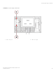
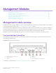
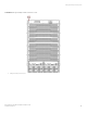
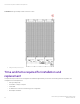
Table Of Contents
- ExtremeRouting SLX 9850-8 Hardware Installation Guide
- Preface
- About this Document
- Device Overview
- Preparing for the Installation
- Mounting the Device
- Initial Setup and Verification
- Initial setup and configuration checklist
- Items required
- Providing power to the device
- Establishing a serial connection
- Configuring a static IP address
- Establishing an Ethernet connection
- Customizing the chassis and host names
- Configuring the DNS service
- Setting the date and time
- Verifying correct operation
- Backing up the configuration
- Powering down the device
- Installing cable management kit
- Monitoring the Device
- Management Modules
- Interface Modules
- Power Supply Modules
- Power supply module overview
- Precautions specific to the power supply module
- Time and items required for removal and replacement
- Removing an AC power supply module
- Inserting an AC power supply module
- Removing a DC power supply module
- Inserting a DC power supply module
- Verifying power supply module operation
- High Voltage Power Supply Unit supporting AC and DC Voltages
- Fan Modules
- Switch Fabric Modules
- Transceivers and cables
- Supported transceivers and cables
- Time and items required
- Precautions specific to transceivers and cables
- Cleaning the fiber-optic connectors
- Managing cables
- Installing an SFP+ transceiver
- Replacing an SFP+ transceiver
- Installing a QSFP28 transceiver
- Replacing a QSFP28 transceiver
- Breakout cables
- Verifying transceiver operation
- Hardware Maintenance Schedule
- ExtremeRouting SLX 9850 Technical Specifications
- System specifications
- Ethernet
- LEDs
- Other
- Weight and physical dimensions
- Environmental requirements
- Power supply specifications (per PSU)
- Power consumption (typical configuration)
- Power consumption (maximum configuration)
- Power consumption (modules) (typical configuration)
- Power consumption (modules) (maximum configuration)
- Data port specifications (Ethernet)
- Serial port specifications (pinout RJ-45)
- Serial port specifications (protocol)
- Memory specifications
- Regulatory compliance (EMC)
- Regulatory compliance (safety)
- Regulatory compliance (environmental)
- Regulatory Statements
- Cautions and Danger Notices

Management Modules
• Management module overview...................................................................................................................................................................87
• Precautions specic to the management modules.............................................................................................................................88
• ESD ground strap connection points........................................................................................................................................................ 88
• Time and items required for installation and replacement................................................................................................................90
• Removing a management module.............................................................................................................................................................91
• Installing a management module................................................................................................................................................................91
• Verifying management module operation...............................................................................................................................................92
Management module overview
Management modules control the hardware components, run the networking protocols, and run the operating system. For a description
of the supported interface modules, refer to Supported hardware and software on page 11.
Each ExtremeRouting SLX 9850 device requires one management module, and can accommodate a second module for redundancy. A
redundant management module works in conjunction with the active management module. If the active module becomes unavailable,
the redundant management module automatically takes over the system operation, minimizing system downtime.
Management modules are hot-swappable, which means you can remove and replace them without powering down the system.
Front panel and port description
The following gure shows the front panel of the management module. The numbered callouts on the illustration are explained in the
callout descriptions after the gure.
FIGURE 41 Management module front panel
1. Service Ethernet port, 10G/1G/100M
2. Auxiliary console port
3. USB port
4. USB port
5. Console port
6. Management Ethernet port, 1G/100M/10M
For description of the LEDs, refer to Interpreting management module LEDs on page 75.
ExtremeRouting SLX 9850-8 Hardware Installation Guide
9035475-02 Rev AA 87