
Installation Guide
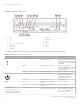
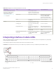
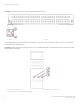

Table Of Contents
- ExtremeRouting SLX 9850-8 Hardware Installation Guide
- Preface
- About this Document
- Device Overview
- Preparing for the Installation
- Mounting the Device
- Initial Setup and Verification
- Initial setup and configuration checklist
- Items required
- Providing power to the device
- Establishing a serial connection
- Configuring a static IP address
- Establishing an Ethernet connection
- Customizing the chassis and host names
- Configuring the DNS service
- Setting the date and time
- Verifying correct operation
- Backing up the configuration
- Powering down the device
- Installing cable management kit
- Monitoring the Device
- Management Modules
- Interface Modules
- Power Supply Modules
- Power supply module overview
- Precautions specific to the power supply module
- Time and items required for removal and replacement
- Removing an AC power supply module
- Inserting an AC power supply module
- Removing a DC power supply module
- Inserting a DC power supply module
- Verifying power supply module operation
- High Voltage Power Supply Unit supporting AC and DC Voltages
- Fan Modules
- Switch Fabric Modules
- Transceivers and cables
- Supported transceivers and cables
- Time and items required
- Precautions specific to transceivers and cables
- Cleaning the fiber-optic connectors
- Managing cables
- Installing an SFP+ transceiver
- Replacing an SFP+ transceiver
- Installing a QSFP28 transceiver
- Replacing a QSFP28 transceiver
- Breakout cables
- Verifying transceiver operation
- Hardware Maintenance Schedule
- ExtremeRouting SLX 9850 Technical Specifications
- System specifications
- Ethernet
- LEDs
- Other
- Weight and physical dimensions
- Environmental requirements
- Power supply specifications (per PSU)
- Power consumption (typical configuration)
- Power consumption (maximum configuration)
- Power consumption (modules) (typical configuration)
- Power consumption (modules) (maximum configuration)
- Data port specifications (Ethernet)
- Serial port specifications (pinout RJ-45)
- Serial port specifications (protocol)
- Memory specifications
- Regulatory compliance (EMC)
- Regulatory compliance (safety)
- Regulatory compliance (environmental)
- Regulatory Statements
- Cautions and Danger Notices

TABLE 21 Interface module LED descriptions (continued)
LED purpose Color Status Recommended action
Flickering green Port is online, with trac owing
through port.
No action is required.
Green steadily blinking on and o
for two seconds at a time
A local fault has been detected Local fault detection can be
conrmed with CLI ex-cli show
local-fault . To clear LED in this
state, congure withshutdown
followed by no shutdown on the
aected interface.
No light (LED is o) Port has no incoming power, or
there is no light or signal carrier
detected.
Verify that the power LED is on.
Check the transceiver and cable.
Polling is in progress. Allow 60 seconds for polling to
complete.
Connected device is congured in
an oine state.
Verify the status of the connected
device.
Ethernet for 36-port 100GbE, 60-
port 40GbE, or 240-port 10GbE
ex-speed interface module
Steady green Port is online (connected to an
external device) but has no trac.
No action is required.
Flickering green Port is online, with trac owing
through port.
No action is required.
Green steadily blinking on and o
for two seconds at a time
A local fault has been detected Local fault detection can be
conrmed with CLI ex-cli show
local-fault . To clear LED in this
state, congure withshutdown
followed by no shutdown on the
aected interface.
No light (LED is o) Port has no incoming power, or
there is no light or signal carrier
detected.
Verify that the power LED is on.
Check the transceiver and cable.
Polling is in progress. Allow 60 seconds for polling to
complete.
Connected device is congured in
an oine state.
Verify the status of the connected
device.
Amber (24 of the 60 ports only) The port is inactive because the
port group has been set to 100G
mode.
The 100G/40G mode is set per
port group. A port group is in fact a
tower. There are 10 ports in a port
group. When a port group is
congured as 100G mode, 4 ports
in the port group are active, and
their Amber LEDs are on.
Interpreting power supply module LEDs
Refer to the following illustrations and table to interpret the LED patterns on the power supply module. The LED patterns may
temporarily change during device diagnostic tests.
Interpreting power supply module LEDs
ExtremeRouting SLX 9850-8 Hardware Installation Guide
80 9035475-02 Rev AA