
Installation Guide
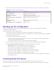
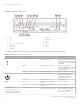
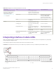
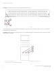

Table Of Contents
- ExtremeRouting SLX 9850-8 Hardware Installation Guide
- Preface
- About this Document
- Device Overview
- Preparing for the Installation
- Mounting the Device
- Initial Setup and Verification
- Initial setup and configuration checklist
- Items required
- Providing power to the device
- Establishing a serial connection
- Configuring a static IP address
- Establishing an Ethernet connection
- Customizing the chassis and host names
- Configuring the DNS service
- Setting the date and time
- Verifying correct operation
- Backing up the configuration
- Powering down the device
- Installing cable management kit
- Monitoring the Device
- Management Modules
- Interface Modules
- Power Supply Modules
- Power supply module overview
- Precautions specific to the power supply module
- Time and items required for removal and replacement
- Removing an AC power supply module
- Inserting an AC power supply module
- Removing a DC power supply module
- Inserting a DC power supply module
- Verifying power supply module operation
- High Voltage Power Supply Unit supporting AC and DC Voltages
- Fan Modules
- Switch Fabric Modules
- Transceivers and cables
- Supported transceivers and cables
- Time and items required
- Precautions specific to transceivers and cables
- Cleaning the fiber-optic connectors
- Managing cables
- Installing an SFP+ transceiver
- Replacing an SFP+ transceiver
- Installing a QSFP28 transceiver
- Replacing a QSFP28 transceiver
- Breakout cables
- Verifying transceiver operation
- Hardware Maintenance Schedule
- ExtremeRouting SLX 9850 Technical Specifications
- System specifications
- Ethernet
- LEDs
- Other
- Weight and physical dimensions
- Environmental requirements
- Power supply specifications (per PSU)
- Power consumption (typical configuration)
- Power consumption (maximum configuration)
- Power consumption (modules) (typical configuration)
- Power consumption (modules) (maximum configuration)
- Data port specifications (Ethernet)
- Serial port specifications (pinout RJ-45)
- Serial port specifications (protocol)
- Memory specifications
- Regulatory compliance (EMC)
- Regulatory compliance (safety)
- Regulatory compliance (environmental)
- Regulatory Statements
- Cautions and Danger Notices

TABLE 20 Management module LED descriptions (continued)
LED purpose Color Status Recommended action
SFMs are hidden behind the fans in
the chassis, use these LEDs to
determine SFM operation. For
more information, refer to
Interpreting switch fabric module
LEDs on page 84.
The SLX 9850 contains a
maximum of six SFMs, but ships
with ve, so not all slots are used.
Steady amber SFM is faulty or initializing. Ensure that the SFM is rmly
seated and check the status by
entering the show chassis
command. If the LED remains
amber, consult the device supplier.
Green Switch fabric module (SFM) module
is operational.
No action is required.
Ethernet Steady green Port is online (connected to an
external device) but has no trac.
No action is required.
Flickering green Port is online, with trac owing
through port.
No action is required.
No light (LED is o) Port has no incoming power, or
there is no light or signal carrier
detected.
Verify that the power LED is on.
Check the transceiver and cable.
Connected device is congured in
an oine state.
Verify the status of the connected
device.
Slow ash (one second on, one
second o)
Device is set to beaconing using
the chassis beacon enable
command.
Disable the beaconing feature by
entering the chassis beacon
disable command.
Interpreting interface module LEDs
Refer to the following illustrations and table to interpret the LED patterns on the interface module. The LED patterns may temporarily
change during device diagnostic tests.
The following two gures show the power and status LEDs in the interface modules.
FIGURE 33 Front panel LEDs for the 36-port 100GbE, 60-port 40GbE, or 240-port 10GbE ex-speed interface module
1. Status 2. Power
Interpreting interface module LEDs
ExtremeRouting SLX 9850-8 Hardware Installation Guide
9035475-02 Rev AA 77