
Installation Guide

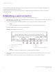


Table Of Contents
- ExtremeRouting SLX 9850-8 Hardware Installation Guide
- Preface
- About this Document
- Device Overview
- Preparing for the Installation
- Mounting the Device
- Initial Setup and Verification
- Initial setup and configuration checklist
- Items required
- Providing power to the device
- Establishing a serial connection
- Configuring a static IP address
- Establishing an Ethernet connection
- Customizing the chassis and host names
- Configuring the DNS service
- Setting the date and time
- Verifying correct operation
- Backing up the configuration
- Powering down the device
- Installing cable management kit
- Monitoring the Device
- Management Modules
- Interface Modules
- Power Supply Modules
- Power supply module overview
- Precautions specific to the power supply module
- Time and items required for removal and replacement
- Removing an AC power supply module
- Inserting an AC power supply module
- Removing a DC power supply module
- Inserting a DC power supply module
- Verifying power supply module operation
- High Voltage Power Supply Unit supporting AC and DC Voltages
- Fan Modules
- Switch Fabric Modules
- Transceivers and cables
- Supported transceivers and cables
- Time and items required
- Precautions specific to transceivers and cables
- Cleaning the fiber-optic connectors
- Managing cables
- Installing an SFP+ transceiver
- Replacing an SFP+ transceiver
- Installing a QSFP28 transceiver
- Replacing a QSFP28 transceiver
- Breakout cables
- Verifying transceiver operation
- Hardware Maintenance Schedule
- ExtremeRouting SLX 9850 Technical Specifications
- System specifications
- Ethernet
- LEDs
- Other
- Weight and physical dimensions
- Environmental requirements
- Power supply specifications (per PSU)
- Power consumption (typical configuration)
- Power consumption (maximum configuration)
- Power consumption (modules) (typical configuration)
- Power consumption (modules) (maximum configuration)
- Data port specifications (Ethernet)
- Serial port specifications (pinout RJ-45)
- Serial port specifications (protocol)
- Memory specifications
- Regulatory compliance (EMC)
- Regulatory compliance (safety)
- Regulatory compliance (environmental)
- Regulatory Statements
- Cautions and Danger Notices
2. Convert each MAC address to a modied EUI-64 format, and then into the nal IPv6 address for the interfaces by performing
the following steps:
a) Remove any punctuation from the MAC.
609c9f46e206
b) Insert
fe after the rst 6 characters.
609c9ffffe46e206
c) Using a calculator application in HEX Mode on a PC, do a Bitwise OR operation of the modied MAC with
0200000000000000.
629c9ffffe46e206
d) Convert the result to IPv6 format by inserting colons after every 4 characters from the right hand side.
629c:9fff:fe46:e206
e) Prepare the IPv6 network information for use. This example uses a sample network of 2001:DB8::/32 provided by the
Admin.
• Normalize the address to a fully expanded format.
2001:0DB8:0000:0000:0000:0000:0000:0000/32
• Remove the cider notation.
2001:0DB8:0000:0000:0000:0000:0000:0000
• Remove the host portion of the address based on a /64 netmask.
2001:0DB8:0000:0000:
• Contract the remaining portion of the address of any leading zeros.
2001:DB8::
f) Combine the IPv6 network
prex from step 2e and the result of step 2d to make the IPv6 address.
2001:DB8::629c:9fff:fe46:e206/32
g) Repeat steps 2a to 2f for each MAC address.
3. Apply the addresses to the appropriate interfaces and congure the default route using the router address provided by the
network administrator.
For more information on conguring management addresses, refer to Extreme SLX-OS Management Guide .
Establishing an Ethernet connection
After using a serial connection to
congure the IP addresses for the device, you can connect the active management module to the local
area network (LAN).
NOTE
Connecting interface modules to a private network or VLAN is recommended.
Establishing an Ethernet connection
ExtremeRouting SLX 9850-8 Hardware Installation Guide
68 9035475-02 Rev AA