
Installation Guide
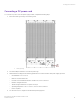

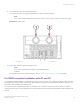


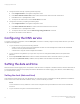
Table Of Contents
- ExtremeRouting SLX 9850-8 Hardware Installation Guide
- Preface
- About this Document
- Device Overview
- Preparing for the Installation
- Mounting the Device
- Initial Setup and Verification
- Initial setup and configuration checklist
- Items required
- Providing power to the device
- Establishing a serial connection
- Configuring a static IP address
- Establishing an Ethernet connection
- Customizing the chassis and host names
- Configuring the DNS service
- Setting the date and time
- Verifying correct operation
- Backing up the configuration
- Powering down the device
- Installing cable management kit
- Monitoring the Device
- Management Modules
- Interface Modules
- Power Supply Modules
- Power supply module overview
- Precautions specific to the power supply module
- Time and items required for removal and replacement
- Removing an AC power supply module
- Inserting an AC power supply module
- Removing a DC power supply module
- Inserting a DC power supply module
- Verifying power supply module operation
- High Voltage Power Supply Unit supporting AC and DC Voltages
- Fan Modules
- Switch Fabric Modules
- Transceivers and cables
- Supported transceivers and cables
- Time and items required
- Precautions specific to transceivers and cables
- Cleaning the fiber-optic connectors
- Managing cables
- Installing an SFP+ transceiver
- Replacing an SFP+ transceiver
- Installing a QSFP28 transceiver
- Replacing a QSFP28 transceiver
- Breakout cables
- Verifying transceiver operation
- Hardware Maintenance Schedule
- ExtremeRouting SLX 9850 Technical Specifications
- System specifications
- Ethernet
- LEDs
- Other
- Weight and physical dimensions
- Environmental requirements
- Power supply specifications (per PSU)
- Power consumption (typical configuration)
- Power consumption (maximum configuration)
- Power consumption (modules) (typical configuration)
- Power consumption (modules) (maximum configuration)
- Data port specifications (Ethernet)
- Serial port specifications (pinout RJ-45)
- Serial port specifications (protocol)
- Memory specifications
- Regulatory compliance (EMC)
- Regulatory compliance (safety)
- Regulatory compliance (environmental)
- Regulatory Statements
- Cautions and Danger Notices

9. Connect the power lugs to the power supply module.
Connect the -48V wire to the negative terminal and the 0V wire to the positive terminal.
NOTE
The DC return must be isolated from the chassis ground (DC-I) when making connections to the power supply.
FIGURE 29 DC power supply
1. DC power lug 1 2. DC power lug 2
10. Plug the other end of the cable into the power source.
NOTE
Do not connect the device to the network until the IP addresses are
congured.
For information about power supply LED patterns, refer to Interpreting power supply module LEDs on page 80.
For NEBS-compliant installation with AC and DC
For the NEBS-compliant installation of the Extreme device with AC and DC systems, use a copper ground wire of at least 2 American
Wire Gauge (AWG). The ground wire should have an agency-approved crimped 2-hole lug (provided with the device) attached to one
end, with the other end attached to building ground.
The connector must be crimped with the proper tool, allowing it to be connected to both ground screws on the enclosure. Before
crimping the ground wire into the provided ground lug, ensure the bare copper wire has been cleaned and antioxidant is applied to the
bare wire.
Providing power to the device
ExtremeRouting SLX 9850-8 Hardware Installation Guide
9035475-02 Rev AA 63