
Installation Guide
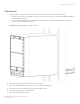
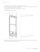
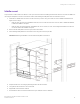
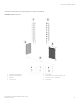
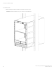
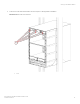
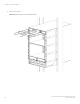

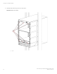
Table Of Contents
- ExtremeRouting SLX 9850-8 Hardware Installation Guide
- Preface
- About this Document
- Device Overview
- Preparing for the Installation
- Mounting the Device
- Initial Setup and Verification
- Initial setup and configuration checklist
- Items required
- Providing power to the device
- Establishing a serial connection
- Configuring a static IP address
- Establishing an Ethernet connection
- Customizing the chassis and host names
- Configuring the DNS service
- Setting the date and time
- Verifying correct operation
- Backing up the configuration
- Powering down the device
- Installing cable management kit
- Monitoring the Device
- Management Modules
- Interface Modules
- Power Supply Modules
- Power supply module overview
- Precautions specific to the power supply module
- Time and items required for removal and replacement
- Removing an AC power supply module
- Inserting an AC power supply module
- Removing a DC power supply module
- Inserting a DC power supply module
- Verifying power supply module operation
- High Voltage Power Supply Unit supporting AC and DC Voltages
- Fan Modules
- Switch Fabric Modules
- Transceivers and cables
- Supported transceivers and cables
- Time and items required
- Precautions specific to transceivers and cables
- Cleaning the fiber-optic connectors
- Managing cables
- Installing an SFP+ transceiver
- Replacing an SFP+ transceiver
- Installing a QSFP28 transceiver
- Replacing a QSFP28 transceiver
- Breakout cables
- Verifying transceiver operation
- Hardware Maintenance Schedule
- ExtremeRouting SLX 9850 Technical Specifications
- System specifications
- Ethernet
- LEDs
- Other
- Weight and physical dimensions
- Environmental requirements
- Power supply specifications (per PSU)
- Power consumption (typical configuration)
- Power consumption (maximum configuration)
- Power consumption (modules) (typical configuration)
- Power consumption (modules) (maximum configuration)
- Data port specifications (Ethernet)
- Serial port specifications (pinout RJ-45)
- Serial port specifications (protocol)
- Memory specifications
- Regulatory compliance (EMC)
- Regulatory compliance (safety)
- Regulatory compliance (environmental)
- Regulatory Statements
- Cautions and Danger Notices

Middle mount
The procedure to install a mid mount device in a two-post rack is the same as installing the device with a ush mount, with the addition of
removing the side plates on the front of the device chassis, and installing the side plates from the recessed mount kit.
1. Install the two saddles from the rack-mount kit for the two-post rack using 12 screws (6 for each saddle) as illustrated in the
gure shown in Step 4.
• If the two-post rack has round, threaded screw holes, use 12 screws from the rack-mount kit, with no additional hardware,
to attach the saddles to the posts.
• If the two-post rack has rectangular, unthreaded holes, use 12 screws, 12 nuts, and 12 alignment washers from the rack-
mount kit to attach the saddles to the posts.
2. Remove the two side plates on the front (port) side of the chassis.
3. Attach the larger side plates from the mid-mount kit using 24 screws (12 per side).
FIGURE 14 Attaching the saddles to the rack and the side plates to the device
4. Prepare the device for mounting by attaching the lift to the device chassis.
5. Using the lift, raise the device to the correct level.
6. If applicable, lock the wheels of the lift.
7. Ensure that the device is oriented so that the front (port side) has access to intake air.
Installing a device on a two-post rack
ExtremeRouting SLX 9850-8 Hardware Installation Guide
9035475-02 Rev AA 43