
Installation Guide
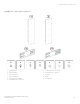
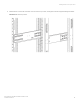
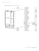
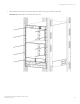
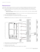
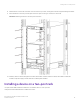
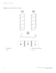
Table Of Contents
- ExtremeRouting SLX 9850-8 Hardware Installation Guide
- Preface
- About this Document
- Device Overview
- Preparing for the Installation
- Mounting the Device
- Initial Setup and Verification
- Initial setup and configuration checklist
- Items required
- Providing power to the device
- Establishing a serial connection
- Configuring a static IP address
- Establishing an Ethernet connection
- Customizing the chassis and host names
- Configuring the DNS service
- Setting the date and time
- Verifying correct operation
- Backing up the configuration
- Powering down the device
- Installing cable management kit
- Monitoring the Device
- Management Modules
- Interface Modules
- Power Supply Modules
- Power supply module overview
- Precautions specific to the power supply module
- Time and items required for removal and replacement
- Removing an AC power supply module
- Inserting an AC power supply module
- Removing a DC power supply module
- Inserting a DC power supply module
- Verifying power supply module operation
- High Voltage Power Supply Unit supporting AC and DC Voltages
- Fan Modules
- Switch Fabric Modules
- Transceivers and cables
- Supported transceivers and cables
- Time and items required
- Precautions specific to transceivers and cables
- Cleaning the fiber-optic connectors
- Managing cables
- Installing an SFP+ transceiver
- Replacing an SFP+ transceiver
- Installing a QSFP28 transceiver
- Replacing a QSFP28 transceiver
- Breakout cables
- Verifying transceiver operation
- Hardware Maintenance Schedule
- ExtremeRouting SLX 9850 Technical Specifications
- System specifications
- Ethernet
- LEDs
- Other
- Weight and physical dimensions
- Environmental requirements
- Power supply specifications (per PSU)
- Power consumption (typical configuration)
- Power consumption (maximum configuration)
- Power consumption (modules) (typical configuration)
- Power consumption (modules) (maximum configuration)
- Data port specifications (Ethernet)
- Serial port specifications (pinout RJ-45)
- Serial port specifications (protocol)
- Memory specifications
- Regulatory compliance (EMC)
- Regulatory compliance (safety)
- Regulatory compliance (environmental)
- Regulatory Statements
- Cautions and Danger Notices

CAUTION
To prevent damage to the chassis and components, never attempt to lift the chassis using the fan or power supply handles.
These handles were not designed to support the weight of the chassis.
Required tools and equipment
The following tools and equipment is required to install the SLX 9850:
• #2 Phillips screwdriver
• 1/4" Hex socket driver
• Pallet jack
• Hydraulic lift or assisted lift, able to raise to a minimum of 140 cm (55 in.), with the ability to support the system weight
NOTE
The system weight varies depending on the type of system, and what modules are installed. To nd the weight of your
device fully populated with the required interface modules, refer to the ExtremeRouting SLX 9850 Technical
Specications on page 131.
Device surface preparation
All surfaces on the Extreme device that are un-plated shall be brought to a bright
nish and treated with an anti-oxidant solution before
connections are made.
All non-conductive surface on the Extreme device shall be removed from all threads and connection points to ensure electrical continuity.
Installing a device on a four-post rack kit
Use part number XBR-SLX9850-8-4PRM-KIT to install the device on a four-post rack.
Verify that the items listed below are included in the rack kit.
Required tools and equipment
ExtremeRouting SLX 9850-8 Hardware Installation Guide
32 9035475-02 Rev AA