
Installation Guide

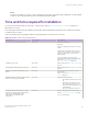
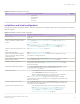
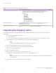

Table Of Contents
- ExtremeRouting SLX 9850-8 Hardware Installation Guide
- Preface
- About this Document
- Device Overview
- Preparing for the Installation
- Mounting the Device
- Initial Setup and Verification
- Initial setup and configuration checklist
- Items required
- Providing power to the device
- Establishing a serial connection
- Configuring a static IP address
- Establishing an Ethernet connection
- Customizing the chassis and host names
- Configuring the DNS service
- Setting the date and time
- Verifying correct operation
- Backing up the configuration
- Powering down the device
- Installing cable management kit
- Monitoring the Device
- Management Modules
- Interface Modules
- Power Supply Modules
- Power supply module overview
- Precautions specific to the power supply module
- Time and items required for removal and replacement
- Removing an AC power supply module
- Inserting an AC power supply module
- Removing a DC power supply module
- Inserting a DC power supply module
- Verifying power supply module operation
- High Voltage Power Supply Unit supporting AC and DC Voltages
- Fan Modules
- Switch Fabric Modules
- Transceivers and cables
- Supported transceivers and cables
- Time and items required
- Precautions specific to transceivers and cables
- Cleaning the fiber-optic connectors
- Managing cables
- Installing an SFP+ transceiver
- Replacing an SFP+ transceiver
- Installing a QSFP28 transceiver
- Replacing a QSFP28 transceiver
- Breakout cables
- Verifying transceiver operation
- Hardware Maintenance Schedule
- ExtremeRouting SLX 9850 Technical Specifications
- System specifications
- Ethernet
- LEDs
- Other
- Weight and physical dimensions
- Environmental requirements
- Power supply specifications (per PSU)
- Power consumption (typical configuration)
- Power consumption (maximum configuration)
- Power consumption (modules) (typical configuration)
- Power consumption (modules) (maximum configuration)
- Data port specifications (Ethernet)
- Serial port specifications (pinout RJ-45)
- Serial port specifications (protocol)
- Memory specifications
- Regulatory compliance (EMC)
- Regulatory compliance (safety)
- Regulatory compliance (environmental)
- Regulatory Statements
- Cautions and Danger Notices

TABLE 16 Installation prerequisites (continued)
Task Task details or additional information Completed
• Subnet mask:
• Default gateway:
• Domain ID:
• Time zone:
Installation and initial conguration
The initial setup includes mounting the device in a rack and completing the conguration tasks necessary to bring the device online and
verify the operation.
TABLE 17 Installation and basic system
conguration
Task Task details or additional information Completed
Mount the device. Choose the two-post or the four-post rack mounting option. Refer to Mounting options
on page 31 .
Install the interface modules, power supply
modules, switch fabric modules, and fan
modules.
Refer to Inserting an interface module on page 95, Inserting an AC power supply
module on page 104, Inserting a switch fabric module on page 117, and Inserting a
fan module on page 111.
Refer to Inserting an interface module on page 95, Inserting an AC power supply
module on page 104 or Inserting a DC power supply module on page 105, Inserting a
switch fabric module on page 117, and Inserting a fan module on page 111.
Gather all components required for the initial
setup.
Refer to Initial Setup and Verication on page 57.
Provide power to the device. Refer to Providing power to the device on page 58.
Attach a management station, establish a
serial connection, and change the default
passwords (optional).
Refer to Establishing a serial connection on page 64. After completing this task, log in
to the serial port to congure the device.
Set the IP address, subnet mask, and the
default gateway IP address.
Use the chassis virtual-ip or chassis virtual-ipv6 command to congure an IP address.
For more information, refer to Conguring a static IP address on page 66.
Establish an Ethernet connection. By establishing an Ethernet connection, you can complete the device conguration
using a serial or Telnet session. Refer to Establishing an Ethernet connection on page
68 for more information.
Customize the chassis and host names. Use the switch-attributes chassis-name and switch-attributes host-name commands
to change the default router name. For more information, refer to the Customizing the
chassis and host names on page 69
Set the date and time.
• Use the clock set command to set the date and time.
• Use the clock timezone command to set the time zone.
• After you congure the system time, use commands in NTP conguration
mode to synchronize the time with an external NTP server.
Refer to Setting the date and time on page 70 for more information. For detailed
command information, refer to the Extreme SLX-OS Management Conguration Guide
for the SLX 9850 Router .
Optional: Congure the DNS service. Use the ip dns domain-name and, if required, ip dns name-server commands to create
DNS server entries. Refer to the Extreme SLX-OS Security Conguration Guide for the
SLX 9850 Router for more information.
Verify that the device operates correctly.
• Check the LEDs to verify operation of module components in the device.
Refer to Interpreting management module LEDs on page 75, Interpreting
interface module LEDs on page 77, Interpreting power supply module
LEDs on page 80, Interpreting fan module LEDs on page 83, and
Interpreting switch fabric module LEDs on page 84.
Quick installation checklists
ExtremeRouting SLX 9850-8 Hardware Installation Guide
9035475-02 Rev AA 27