
Installation Guide
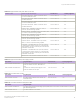
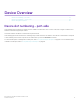
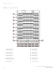
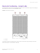
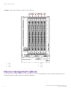
Table Of Contents
- ExtremeRouting SLX 9850-8 Hardware Installation Guide
- Preface
- About this Document
- Device Overview
- Preparing for the Installation
- Mounting the Device
- Initial Setup and Verification
- Initial setup and configuration checklist
- Items required
- Providing power to the device
- Establishing a serial connection
- Configuring a static IP address
- Establishing an Ethernet connection
- Customizing the chassis and host names
- Configuring the DNS service
- Setting the date and time
- Verifying correct operation
- Backing up the configuration
- Powering down the device
- Installing cable management kit
- Monitoring the Device
- Management Modules
- Interface Modules
- Power Supply Modules
- Power supply module overview
- Precautions specific to the power supply module
- Time and items required for removal and replacement
- Removing an AC power supply module
- Inserting an AC power supply module
- Removing a DC power supply module
- Inserting a DC power supply module
- Verifying power supply module operation
- High Voltage Power Supply Unit supporting AC and DC Voltages
- Fan Modules
- Switch Fabric Modules
- Transceivers and cables
- Supported transceivers and cables
- Time and items required
- Precautions specific to transceivers and cables
- Cleaning the fiber-optic connectors
- Managing cables
- Installing an SFP+ transceiver
- Replacing an SFP+ transceiver
- Installing a QSFP28 transceiver
- Replacing a QSFP28 transceiver
- Breakout cables
- Verifying transceiver operation
- Hardware Maintenance Schedule
- ExtremeRouting SLX 9850 Technical Specifications
- System specifications
- Ethernet
- LEDs
- Other
- Weight and physical dimensions
- Environmental requirements
- Power supply specifications (per PSU)
- Power consumption (typical configuration)
- Power consumption (maximum configuration)
- Power consumption (modules) (typical configuration)
- Power consumption (modules) (maximum configuration)
- Data port specifications (Ethernet)
- Serial port specifications (pinout RJ-45)
- Serial port specifications (protocol)
- Memory specifications
- Regulatory compliance (EMC)
- Regulatory compliance (safety)
- Regulatory compliance (environmental)
- Regulatory Statements
- Cautions and Danger Notices

Device slot numbering - nonport-side
The following illustration shows the nonport-side view of the SLX 9850-8. The callouts in the illustration correspond to the numbering of
the fan modules in the chassis when you enter the show slots command.
FIGURE 2 Nonport side of the SLX 9850-8
1. Fan module 1
2. Fan module 2
3. Fan module 3
The switch fabric modules are located behind the fans. There are six slots for the switch fabric modules. Numbering for the modules
goes from left to right, with 1 on the far left and 6 on the far right.
Device slot numbering - nonport-side
ExtremeRouting SLX 9850-8 Hardware Installation Guide
9035475-02 Rev AA 19