
Installation Guide
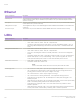
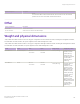
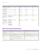
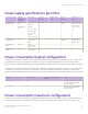
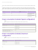
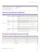
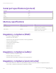

Table Of Contents
- ExtremeRouting SLX 9850-8 Hardware Installation Guide
- Preface
- About this Document
- Device Overview
- Preparing for the Installation
- Mounting the Device
- Initial Setup and Verification
- Initial setup and configuration checklist
- Items required
- Providing power to the device
- Establishing a serial connection
- Configuring a static IP address
- Establishing an Ethernet connection
- Customizing the chassis and host names
- Configuring the DNS service
- Setting the date and time
- Verifying correct operation
- Backing up the configuration
- Powering down the device
- Installing cable management kit
- Monitoring the Device
- Management Modules
- Interface Modules
- Power Supply Modules
- Power supply module overview
- Precautions specific to the power supply module
- Time and items required for removal and replacement
- Removing an AC power supply module
- Inserting an AC power supply module
- Removing a DC power supply module
- Inserting a DC power supply module
- Verifying power supply module operation
- High Voltage Power Supply Unit supporting AC and DC Voltages
- Fan Modules
- Switch Fabric Modules
- Transceivers and cables
- Supported transceivers and cables
- Time and items required
- Precautions specific to transceivers and cables
- Cleaning the fiber-optic connectors
- Managing cables
- Installing an SFP+ transceiver
- Replacing an SFP+ transceiver
- Installing a QSFP28 transceiver
- Replacing a QSFP28 transceiver
- Breakout cables
- Verifying transceiver operation
- Hardware Maintenance Schedule
- ExtremeRouting SLX 9850 Technical Specifications
- System specifications
- Ethernet
- LEDs
- Other
- Weight and physical dimensions
- Environmental requirements
- Power supply specifications (per PSU)
- Power consumption (typical configuration)
- Power consumption (maximum configuration)
- Power consumption (modules) (typical configuration)
- Power consumption (modules) (maximum configuration)
- Data port specifications (Ethernet)
- Serial port specifications (pinout RJ-45)
- Serial port specifications (protocol)
- Memory specifications
- Regulatory compliance (EMC)
- Regulatory compliance (safety)
- Regulatory compliance (environmental)
- Regulatory Statements
- Cautions and Danger Notices

Ethernet
System component Description
QSFP28 ports The QSFP28 ports are available on 36-port 100GbE ex-speed interface module. The 36-port 100GbE
interface modules supports 36-port 100GbE, 60-port 40GbE, or 240-port 10GbE and requires QSFP28
optics for connectivity.
SFP+ ports The SFP+ ports are available on 72-port 10GbE/1GbE interface module. The 72-port 10GbE/1GbE interface
module requires SFP+ ports for connectivity.
Management RJ-45 port The management RJ-45 port on the MM management interface labeled MANAGEMENT for 1G/100M/10M
connectivity.
Service RJ-45 port The service RJ-45 port on the MM service interface labeled SERVICE for 10G/1G/100M connectivity
LEDs
System component Description
Interface module LEDs
• Power: Green - Power OK, o - No power
• Status: Green- Status OK, Amber - Error; O - Unexpected error
• Link status (1 LED per physical port): Green (Solid) - Link is up; Green (Blinking rapidly) - Link is up
and running trac; Green (Blinking on and o for two seconds at a time) - Local fault detected; O -
No link
Management module LEDs
• Power: Green - Power OK, o - No power
• Status: Green- Status OK, Amber - Error, O - Unexpected error
• Active: O - This management module is in Standby mode; Blue - This is the active management
module.
• Switch fabric module status: Green - switch fabric module OK; Amber - error; O - Unexpected error
• Ethernet: Green (Solid) - Link is up; Green (Blinking) - Link is up and running trac; O - No link;
Amber (some ex module ports): module is in 100G mode and these ports are inactive
Switch fabric module LEDs
• Power: Green - Power OK; o - No power
• Switch fabric module status: Amber - Error
NOTE
There is a switch fabric module status LED on the front panel of the Fan module.
Power supply LEDs
• LED 1 and LED 2: Steady Green - Input and output voltages are within range
• LED 1: O and LED 2: Flashing Yellow - Power supply does not have incoming power and is not
providing power to the device, or the Input AC voltage is out of range.
• LED 1: Green and LED 2: Yellow - Output voltage is out of range
• LED 1: Green and LED 2: Flashing Yellow/Green - Over-temperature warning or fan error
Fan module LEDs
• Power (Fan) LED: No light (LED is o) - Fan assembly does not have power. Steady green - Fan
assembly has power.
• Status (Fan) LED: No light (LED is o) - Fan assembly is either healthy or does not have power. Steady
amber - Fan assembly is being initialized or has a failure (full or partial).
• Power (SFM) LED: No light (LED is o) - One or more SFM module is not powered on. Green -
Module is operational.
• Status (SFM) LED: No light (LED is o) - One or more SFM module is either not operational or does
not have power. Amber - Module is faulty or initializing. Green - Module is operational.
Ethernet
ExtremeRouting SLX 9850-8 Hardware Installation Guide
132 9035475-02 Rev AA