
Installation Guide
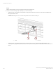
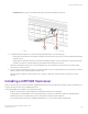

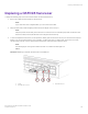
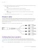

Table Of Contents
- ExtremeRouting SLX 9850-8 Hardware Installation Guide
- Preface
- About this Document
- Device Overview
- Preparing for the Installation
- Mounting the Device
- Initial Setup and Verification
- Initial setup and configuration checklist
- Items required
- Providing power to the device
- Establishing a serial connection
- Configuring a static IP address
- Establishing an Ethernet connection
- Customizing the chassis and host names
- Configuring the DNS service
- Setting the date and time
- Verifying correct operation
- Backing up the configuration
- Powering down the device
- Installing cable management kit
- Monitoring the Device
- Management Modules
- Interface Modules
- Power Supply Modules
- Power supply module overview
- Precautions specific to the power supply module
- Time and items required for removal and replacement
- Removing an AC power supply module
- Inserting an AC power supply module
- Removing a DC power supply module
- Inserting a DC power supply module
- Verifying power supply module operation
- High Voltage Power Supply Unit supporting AC and DC Voltages
- Fan Modules
- Switch Fabric Modules
- Transceivers and cables
- Supported transceivers and cables
- Time and items required
- Precautions specific to transceivers and cables
- Cleaning the fiber-optic connectors
- Managing cables
- Installing an SFP+ transceiver
- Replacing an SFP+ transceiver
- Installing a QSFP28 transceiver
- Replacing a QSFP28 transceiver
- Breakout cables
- Verifying transceiver operation
- Hardware Maintenance Schedule
- ExtremeRouting SLX 9850 Technical Specifications
- System specifications
- Ethernet
- LEDs
- Other
- Weight and physical dimensions
- Environmental requirements
- Power supply specifications (per PSU)
- Power consumption (typical configuration)
- Power consumption (maximum configuration)
- Power consumption (modules) (typical configuration)
- Power consumption (modules) (maximum configuration)
- Data port specifications (Ethernet)
- Serial port specifications (pinout RJ-45)
- Serial port specifications (protocol)
- Memory specifications
- Regulatory compliance (EMC)
- Regulatory compliance (safety)
- Regulatory compliance (environmental)
- Regulatory Statements
- Cautions and Danger Notices

FIGURE 63 Installing an SFP+ transceiver with bail latch into the interface module port
1. Bail
Transceivers are keyed so that they can only be inserted with the correct orientation. If a transceiver does not slide in easily,
ensure that it is correctly oriented.
2. Position a cable so that the key (the ridge on one side of the cable connector) is aligned with the slot in the transceiver. Insert the
cable into the transceiver until the latching mechanism clicks.
NOTE
Cables are keyed so that they can be inserted in only one way. If a cable does not slide in easily, ensure that it is
correctly oriented. Do not insert any unsupported cable intended for an other type of transceiver into a regular SFP+
transceiver. You may damage the cable as well as the transceiver.
Replacing an SFP+ transceiver
Complete the following steps to remove and then install a new SFP+ transceiver.
1. Remove any cables that are inserted into the transceiver.
Replacing an SFP+ transceiver
ExtremeRouting SLX 9850-8 Hardware Installation Guide
9035475-02 Rev AA 123