
Installation Guide

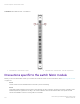
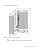

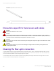
Table Of Contents
- ExtremeRouting SLX 9850-8 Hardware Installation Guide
- Preface
- About this Document
- Device Overview
- Preparing for the Installation
- Mounting the Device
- Initial Setup and Verification
- Initial setup and configuration checklist
- Items required
- Providing power to the device
- Establishing a serial connection
- Configuring a static IP address
- Establishing an Ethernet connection
- Customizing the chassis and host names
- Configuring the DNS service
- Setting the date and time
- Verifying correct operation
- Backing up the configuration
- Powering down the device
- Installing cable management kit
- Monitoring the Device
- Management Modules
- Interface Modules
- Power Supply Modules
- Power supply module overview
- Precautions specific to the power supply module
- Time and items required for removal and replacement
- Removing an AC power supply module
- Inserting an AC power supply module
- Removing a DC power supply module
- Inserting a DC power supply module
- Verifying power supply module operation
- High Voltage Power Supply Unit supporting AC and DC Voltages
- Fan Modules
- Switch Fabric Modules
- Transceivers and cables
- Supported transceivers and cables
- Time and items required
- Precautions specific to transceivers and cables
- Cleaning the fiber-optic connectors
- Managing cables
- Installing an SFP+ transceiver
- Replacing an SFP+ transceiver
- Installing a QSFP28 transceiver
- Replacing a QSFP28 transceiver
- Breakout cables
- Verifying transceiver operation
- Hardware Maintenance Schedule
- ExtremeRouting SLX 9850 Technical Specifications
- System specifications
- Ethernet
- LEDs
- Other
- Weight and physical dimensions
- Environmental requirements
- Power supply specifications (per PSU)
- Power consumption (typical configuration)
- Power consumption (maximum configuration)
- Power consumption (modules) (typical configuration)
- Power consumption (modules) (maximum configuration)
- Data port specifications (Ethernet)
- Serial port specifications (pinout RJ-45)
- Serial port specifications (protocol)
- Memory specifications
- Regulatory compliance (EMC)
- Regulatory compliance (safety)
- Regulatory compliance (environmental)
- Regulatory Statements
- Cautions and Danger Notices

In addition, wear a wrist grounding strap connected to chassis ground (if the device is plugged in) or a bench ground. Refer to ESD
ground strap connection points on page 88 for the location of the ESD jack.
DANGER
For safety reasons, the ESD wrist strap should contain a series 1 megaohm resistor.
Time and items required for replacement
The replacement procedure for the switch fabric module takes approximately 15 minutes (5 minutes to remove the fan module, and 10
minutes to remove the switch fabric module. Extreme recommends replacement to approximately 20 minutes to include inserting the
replacement switch fabric module.
The following items are required for the switch fabric module replacement:
• ESD grounding strap
• #2 Phillips screwdriver
• Replacement switch fabric module
NOTE
The ambient intake temperature of the system must be less than 35 deg C (95 deg F) at sea level to prevent overheating. If the
ambient temperature is greater than 35 deg C, the module installation time must be reduced. Refer to the specic module
removal and installation instructions in this guide for more details.
Removing a switch fabric module
You can continue to operate the device while a switch fabric module (SFM) is being replaced.
Complete the following steps to remove an SFM. Refer to the illustration provided with the procedure.
1. Determine which fan module needs to be removed by performing one or both of the following steps.
• Refer to the sticker on the rear of the chassis, below the fans, that provides a graphic representation of the SFMs behind
each fan module.
• Find the fan module that has the SFM Fault LED lit, and remove this fan module.
2. Remove the fan module to access the SFM. Refer to Removing a fan module on page 110 for this procedure.
NOTE
The fan needs to be replaced within 2 minutes if the ambient temperature exceeds 35 deg C (95 deg F).
3. Unscrew the two captive screws on the top and the bottom of the SFM using the #2 Phillips screwdriver.
• The use of a long handled #2 Phillips screwdriver is recommended although not required.
• While operating or turning the thumbscrew on SFMs during installation and removal of the blade, insure that the ejector is
held in the closed position. This insures ease of operation of the thumbscrew and insures that the screw is either fully
seated while installing or is fully disengaged while removing the blade. In order to insure the ejector is held in the closed
position, the user may need to hold the ejector down by hand during operation or turning the thumbscrew.
4. Open the ejectors on the top and bottom of the SFM by rotating them outward towards you.
Removing a switch fabric module
ExtremeRouting SLX 9850-8 Hardware Installation Guide
9035475-02 Rev AA 115