
Installation Guide


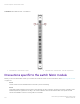
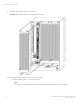

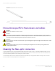
Table Of Contents
- ExtremeRouting SLX 9850-8 Hardware Installation Guide
- Preface
- About this Document
- Device Overview
- Preparing for the Installation
- Mounting the Device
- Initial Setup and Verification
- Initial setup and configuration checklist
- Items required
- Providing power to the device
- Establishing a serial connection
- Configuring a static IP address
- Establishing an Ethernet connection
- Customizing the chassis and host names
- Configuring the DNS service
- Setting the date and time
- Verifying correct operation
- Backing up the configuration
- Powering down the device
- Installing cable management kit
- Monitoring the Device
- Management Modules
- Interface Modules
- Power Supply Modules
- Power supply module overview
- Precautions specific to the power supply module
- Time and items required for removal and replacement
- Removing an AC power supply module
- Inserting an AC power supply module
- Removing a DC power supply module
- Inserting a DC power supply module
- Verifying power supply module operation
- High Voltage Power Supply Unit supporting AC and DC Voltages
- Fan Modules
- Switch Fabric Modules
- Transceivers and cables
- Supported transceivers and cables
- Time and items required
- Precautions specific to transceivers and cables
- Cleaning the fiber-optic connectors
- Managing cables
- Installing an SFP+ transceiver
- Replacing an SFP+ transceiver
- Installing a QSFP28 transceiver
- Replacing a QSFP28 transceiver
- Breakout cables
- Verifying transceiver operation
- Hardware Maintenance Schedule
- ExtremeRouting SLX 9850 Technical Specifications
- System specifications
- Ethernet
- LEDs
- Other
- Weight and physical dimensions
- Environmental requirements
- Power supply specifications (per PSU)
- Power consumption (typical configuration)
- Power consumption (maximum configuration)
- Power consumption (modules) (typical configuration)
- Power consumption (modules) (maximum configuration)
- Data port specifications (Ethernet)
- Serial port specifications (pinout RJ-45)
- Serial port specifications (protocol)
- Memory specifications
- Regulatory compliance (EMC)
- Regulatory compliance (safety)
- Regulatory compliance (environmental)
- Regulatory Statements
- Cautions and Danger Notices

Switch Fabric Modules
• Switch fabric module overview................................................................................................................................................................. 113
• Precautions specic to the switch fabric module..............................................................................................................................114
• Time and items required for replacement............................................................................................................................................ 115
• Removing a switch fabric module........................................................................................................................................................... 115
• Inserting a switch fabric module...............................................................................................................................................................117
• Verifying switch fabric module operation............................................................................................................................................. 118
Switch fabric module overview
The switch fabric modules (SFMs) forward trac between ports and the interface modules.
By default, ve SFMs are installed in an ExtremeRouting SLX 9850 device chassis. At least one SFM is required for system operation. A
failure of any single SFM does not cause the system to completely fail.
If an SFM fails, the SFM LED on the management module and fan module displays amber, showing which SFM has failed, and a syslog
message is created. System trac is automatically is re-balanced to other SFMs.
The following gure shows a SFM and the LEDs on the SFM. Since the SFM is behind the fan, these LEDs cannot be seen unless the
fan is removed.
NOTE
To check the status of the SFM without removing the fan, SFM status LEDs are provided on the fan and management
modules. For information about the SFM LEDs on the fan module, refer to Interpreting switch fabric module LEDs on page 84.
For information about the SFM LEDs on the management module, refer to Interpreting management module LEDs on page
75.
ExtremeRouting SLX 9850-8 Hardware Installation Guide
9035475-02 Rev AA 113