
Installation Guide

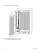

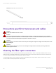
Table Of Contents
- ExtremeRouting SLX 9850-8 Hardware Installation Guide
- Preface
- About this Document
- Device Overview
- Preparing for the Installation
- Mounting the Device
- Initial Setup and Verification
- Initial setup and configuration checklist
- Items required
- Providing power to the device
- Establishing a serial connection
- Configuring a static IP address
- Establishing an Ethernet connection
- Customizing the chassis and host names
- Configuring the DNS service
- Setting the date and time
- Verifying correct operation
- Backing up the configuration
- Powering down the device
- Installing cable management kit
- Monitoring the Device
- Management Modules
- Interface Modules
- Power Supply Modules
- Power supply module overview
- Precautions specific to the power supply module
- Time and items required for removal and replacement
- Removing an AC power supply module
- Inserting an AC power supply module
- Removing a DC power supply module
- Inserting a DC power supply module
- Verifying power supply module operation
- High Voltage Power Supply Unit supporting AC and DC Voltages
- Fan Modules
- Switch Fabric Modules
- Transceivers and cables
- Supported transceivers and cables
- Time and items required
- Precautions specific to transceivers and cables
- Cleaning the fiber-optic connectors
- Managing cables
- Installing an SFP+ transceiver
- Replacing an SFP+ transceiver
- Installing a QSFP28 transceiver
- Replacing a QSFP28 transceiver
- Breakout cables
- Verifying transceiver operation
- Hardware Maintenance Schedule
- ExtremeRouting SLX 9850 Technical Specifications
- System specifications
- Ethernet
- LEDs
- Other
- Weight and physical dimensions
- Environmental requirements
- Power supply specifications (per PSU)
- Power consumption (typical configuration)
- Power consumption (maximum configuration)
- Power consumption (modules) (typical configuration)
- Power consumption (modules) (maximum configuration)
- Data port specifications (Ethernet)
- Serial port specifications (pinout RJ-45)
- Serial port specifications (protocol)
- Memory specifications
- Regulatory compliance (EMC)
- Regulatory compliance (safety)
- Regulatory compliance (environmental)
- Regulatory Statements
- Cautions and Danger Notices
Inserting a fan module
Complete the following steps to replace the fan in a chassis. Refer to the illustration provided in Figure 58 on page 110.
NOTE
The SFM LED should transit to the OK state after approximately 30 seconds if all SFMs are OK on insertion.
1. Orient the fan and slide it into the chassis, supporting the fan from beneath as you install it, and pushing rmly to ensure that it
is seated.
2. Use the screwdriver to tighten the four captive screws (two each at the top and bottom of the module).
3. Verify that the fan module power LED displays a green light.
Verifying fan module operation
To verify fan module operation, complete the following steps.
1. Check the LEDs on the fan module to verify correct operation. For information about interpreting LED patterns, refer to
Interpreting fan module LEDs on page 83.
2. Enter the show environment fan command and note any error conditions.
Air
lter replacement schedule
The air lter is only used with systems that include a NEBS kit for NEBS compliance.
You can remove and replace an air lter when it gets too clogged with dirt and dust to operate eciently. You should perform regular
physical inspections to determine how often to replace the air lter. Maintaining clean air lters ensures optimal airow through the
devices.
Based on the trac and particulate levels of the installation location, the site operator should determine the appropriate replacement
intervals for the air lter. If the air lter were to become suciently blocked, the thermal policy of the device would notify the administrator
of an environmental issue with the system.
If a site-specic interval cannot be determined by the site operator, the lter should be replaced on an interval of every 3 months.
For more information about replacing the fan lter, refer to the NEBS manual for this device.
Air lter replacement schedule
ExtremeRouting SLX 9850-8 Hardware Installation Guide
9035475-02 Rev AA 111