
Installation Guide
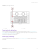
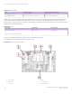
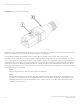
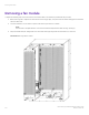
Table Of Contents
- ExtremeRouting SLX 9850-8 Hardware Installation Guide
- Preface
- About this Document
- Device Overview
- Preparing for the Installation
- Mounting the Device
- Initial Setup and Verification
- Initial setup and configuration checklist
- Items required
- Providing power to the device
- Establishing a serial connection
- Configuring a static IP address
- Establishing an Ethernet connection
- Customizing the chassis and host names
- Configuring the DNS service
- Setting the date and time
- Verifying correct operation
- Backing up the configuration
- Powering down the device
- Installing cable management kit
- Monitoring the Device
- Management Modules
- Interface Modules
- Power Supply Modules
- Power supply module overview
- Precautions specific to the power supply module
- Time and items required for removal and replacement
- Removing an AC power supply module
- Inserting an AC power supply module
- Removing a DC power supply module
- Inserting a DC power supply module
- Verifying power supply module operation
- High Voltage Power Supply Unit supporting AC and DC Voltages
- Fan Modules
- Switch Fabric Modules
- Transceivers and cables
- Supported transceivers and cables
- Time and items required
- Precautions specific to transceivers and cables
- Cleaning the fiber-optic connectors
- Managing cables
- Installing an SFP+ transceiver
- Replacing an SFP+ transceiver
- Installing a QSFP28 transceiver
- Replacing a QSFP28 transceiver
- Breakout cables
- Verifying transceiver operation
- Hardware Maintenance Schedule
- ExtremeRouting SLX 9850 Technical Specifications
- System specifications
- Ethernet
- LEDs
- Other
- Weight and physical dimensions
- Environmental requirements
- Power supply specifications (per PSU)
- Power consumption (typical configuration)
- Power consumption (maximum configuration)
- Power consumption (modules) (typical configuration)
- Power consumption (modules) (maximum configuration)
- Data port specifications (Ethernet)
- Serial port specifications (pinout RJ-45)
- Serial port specifications (protocol)
- Memory specifications
- Regulatory compliance (EMC)
- Regulatory compliance (safety)
- Regulatory compliance (environmental)
- Regulatory Statements
- Cautions and Danger Notices

Fan Modules
• Fan module overview....................................................................................................................................................................................109
• Precautions specic to the fan module.................................................................................................................................................109
• Time and items required for replacement............................................................................................................................................ 109
• Removing a fan module.............................................................................................................................................................................. 110
• Inserting a fan module..................................................................................................................................................................................111
• Verifying fan module operation.................................................................................................................................................................111
• Air lter replacement schedule..................................................................................................................................................................111
Fan module overview
The fan modules provide air cooling for the device. Each device contains three fan modules. Each fan module for the ExtremeRouting
SLX 9850-8 device contains four fans. The fan airow enters from the port side and exits from the fan side of the device.
For a description of the fan module LEDs, refer to Interpreting fan module LEDs on page 83.
This section describes the procedures you perform to remove and insert a fan module.
Precautions specic to the fan module
The device can continue to operate during the fan replacement procedure for 20 minutes. If the system reaches an over temperature
condition, it automatically sends a warning message. When the critical temperature is reached, the system shuts down.
NOTE
The ambient intake temperature of the system must be less than 35 deg C (95 deg F) at sea level to prevent overheating. If the
ambient temperature is greater than 35 deg C, the module installation time must be reduced. Refer to the specic module
removal and installation instructions in this guide for more details.
Time and items required for replacement
The replacement procedure for each fan takes less than 5 minutes. The following items are required for the fan replacement:
• Replacement fan
• #2 Phillips screwdriver
NOTE
The ambient intake temperature of the system must be less than 35 deg C (95 deg F) at sea level to prevent overheating. If the
ambient temperature is greater than 35 deg C, the module installation time must be reduced. Refer to the specic module
removal and installation instructions in this guide for more details.
ExtremeRouting SLX 9850-8 Hardware Installation Guide
9035475-02 Rev AA 109