
Installation Guide
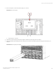
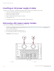
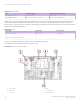
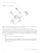
Table Of Contents
- ExtremeRouting SLX 9850-8 Hardware Installation Guide
- Preface
- About this Document
- Device Overview
- Preparing for the Installation
- Mounting the Device
- Initial Setup and Verification
- Initial setup and configuration checklist
- Items required
- Providing power to the device
- Establishing a serial connection
- Configuring a static IP address
- Establishing an Ethernet connection
- Customizing the chassis and host names
- Configuring the DNS service
- Setting the date and time
- Verifying correct operation
- Backing up the configuration
- Powering down the device
- Installing cable management kit
- Monitoring the Device
- Management Modules
- Interface Modules
- Power Supply Modules
- Power supply module overview
- Precautions specific to the power supply module
- Time and items required for removal and replacement
- Removing an AC power supply module
- Inserting an AC power supply module
- Removing a DC power supply module
- Inserting a DC power supply module
- Verifying power supply module operation
- High Voltage Power Supply Unit supporting AC and DC Voltages
- Fan Modules
- Switch Fabric Modules
- Transceivers and cables
- Supported transceivers and cables
- Time and items required
- Precautions specific to transceivers and cables
- Cleaning the fiber-optic connectors
- Managing cables
- Installing an SFP+ transceiver
- Replacing an SFP+ transceiver
- Installing a QSFP28 transceiver
- Replacing a QSFP28 transceiver
- Breakout cables
- Verifying transceiver operation
- Hardware Maintenance Schedule
- ExtremeRouting SLX 9850 Technical Specifications
- System specifications
- Ethernet
- LEDs
- Other
- Weight and physical dimensions
- Environmental requirements
- Power supply specifications (per PSU)
- Power consumption (typical configuration)
- Power consumption (maximum configuration)
- Power consumption (modules) (typical configuration)
- Power consumption (modules) (maximum configuration)
- Data port specifications (Ethernet)
- Serial port specifications (pinout RJ-45)
- Serial port specifications (protocol)
- Memory specifications
- Regulatory compliance (EMC)
- Regulatory compliance (safety)
- Regulatory compliance (environmental)
- Regulatory Statements
- Cautions and Danger Notices

FIGURE 57 Power Cord Connector PSU side
1. Latch 2. Cord plug
Integral latch on plug prevents accidental disconnect of connectors under load thus ensuring that connectors remain properly mated. On
SAF-D connector on PSU, power cord is latched at bottom of plug in connector picture.
Unterminated wires enables full customization by the customers based on application (HVAC/HVDC) and country plug type.
SLX 9850-8 can accommodate up to 12 power supplies in 6+6 full redundant conguration. Only six PSUs are required at any given
time to support all possible congurations with present or future blades. Customers are recommended to have 12 PSUs installed to get
to full 6+6 redundant conguration. For those SKUs without PSUs (reverse airows), PSU needs to be added individually. SLX 9850-8
requires 6+1 to 6+6 PSU congurations otherwise the SLX-OS considers the switch to be in a Marginal state. All PSUs in the chassis
must of same kind i.e. all PSUs must be 240V AC PSUs or all PSUs must be High Voltage PSUs. Mixing of 240V AC and High Voltage
PSUs in same chassis is not supported.
NOTE
Mixing of Regular AC and HV PSUs in a single chassis is not supported.
NOTE
HV PSUs will be supported only on "build to order" base chassis SKU namely [Fusion Chassis P/Ns]. These oerings do not
include PSUs or Fans. PSUs and Fans must be added based on the customer power requirements. This arrangement allows
assembling chassis as per customer requirements (HV PSU or 240V AC PSU). No new base director chassis P/Ns will be
created that includes HV PSUs.
High Voltage Power Supply Unit supporting AC and DC Voltages
ExtremeRouting SLX 9850-8 Hardware Installation Guide
108 9035475-02 Rev AA