
Installation Guide
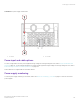
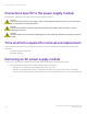
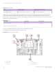
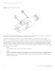
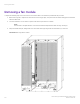
Table Of Contents
- ExtremeRouting SLX 9850-8 Hardware Installation Guide
- Preface
- About this Document
- Device Overview
- Preparing for the Installation
- Mounting the Device
- Initial Setup and Verification
- Initial setup and configuration checklist
- Items required
- Providing power to the device
- Establishing a serial connection
- Configuring a static IP address
- Establishing an Ethernet connection
- Customizing the chassis and host names
- Configuring the DNS service
- Setting the date and time
- Verifying correct operation
- Backing up the configuration
- Powering down the device
- Installing cable management kit
- Monitoring the Device
- Management Modules
- Interface Modules
- Power Supply Modules
- Power supply module overview
- Precautions specific to the power supply module
- Time and items required for removal and replacement
- Removing an AC power supply module
- Inserting an AC power supply module
- Removing a DC power supply module
- Inserting a DC power supply module
- Verifying power supply module operation
- High Voltage Power Supply Unit supporting AC and DC Voltages
- Fan Modules
- Switch Fabric Modules
- Transceivers and cables
- Supported transceivers and cables
- Time and items required
- Precautions specific to transceivers and cables
- Cleaning the fiber-optic connectors
- Managing cables
- Installing an SFP+ transceiver
- Replacing an SFP+ transceiver
- Installing a QSFP28 transceiver
- Replacing a QSFP28 transceiver
- Breakout cables
- Verifying transceiver operation
- Hardware Maintenance Schedule
- ExtremeRouting SLX 9850 Technical Specifications
- System specifications
- Ethernet
- LEDs
- Other
- Weight and physical dimensions
- Environmental requirements
- Power supply specifications (per PSU)
- Power consumption (typical configuration)
- Power consumption (maximum configuration)
- Power consumption (modules) (typical configuration)
- Power consumption (modules) (maximum configuration)
- Data port specifications (Ethernet)
- Serial port specifications (pinout RJ-45)
- Serial port specifications (protocol)
- Memory specifications
- Regulatory compliance (EMC)
- Regulatory compliance (safety)
- Regulatory compliance (environmental)
- Regulatory Statements
- Cautions and Danger Notices

The PSU supports one INPUT and one OUTPUT LED for status indication of PSU. The table below indicates the status LED color and
their meaning.
TABLE 27 HV PSU Status LED Denitions
Type LED Denitions
Power supply LEDs
• LED 1 and LED 2: Steady Green - Input and output voltages
are within range
• LED 1: O and LED 2: Flashing Yellow - Power supply does
not have incoming power and is not providing power to the
device, or the Input AC voltage is out of range.
• LED 1: Green and LED 2: Yellow - Output voltage is out of
range
• LED 1: Green and LED 2: Flashing Yellow/Green - Over-
temperature warning or fan error
This PSU will provide full output power of 3000W when operating with input voltage of 192 to 400 VDC. Operation at low line (90 -
132 VAC) will deliver reduced power.
Connector Type
High Voltage power supply unit have Anderson SAF-D connector. SAF-D connector types is size compatible with the IEC 320 C13 and
C14 AC connector types. Note that connector on HV PSU is not ush to the PSU as in the 240V AC PSU.
Power Cords
The HV PSU uses the SAF-D-Grid connector on the line side (HVAC/DC Input side) currently made by Anderson Power Products as
described in the connector type section. High Voltage input power is provided to the chassis by means of up to 6 detachable power
cords for F4 and up to 12 detachable line cords for F8. This power cord will have Saf-D-Grid
®
400 plug on PSU side and unterminated
3 wires to the outlet. The plug on PSU side is shown below:
High Voltage Power Supply Unit supporting AC and DC Voltages
ExtremeRouting SLX 9850-8 Hardware Installation Guide
9035475-02 Rev AA 107