
Installation Guide

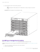


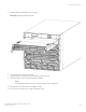

Table Of Contents
- ExtremeRouting SLX 9850-4 Hardware Installation Guide
- Preface
- About this Document
- Device Overview
- Preparing for the Installation
- Mounting the Device
- Initial Setup and Verification
- Initial setup and configuration checklist
- Items required
- Providing power to the device
- Establishing a serial connection
- Configuring a static IP address
- Establishing an Ethernet connection
- Customizing the chassis and host names
- Configuring the DNS service
- Setting the date and time
- Verifying correct operation
- Backing up the configuration
- Powering down the device
- Installing cable management kit
- Monitoring the Device
- Management Modules
- Interface Modules
- Power Supply Modules
- Power supply module overview
- Precautions specific to the power supply module
- Time and items required for removal and replacement
- Removing an AC power supply module
- Inserting an AC power supply module
- Removing a DC power supply module
- Inserting a DC power supply module
- Verifying power supply module operation
- High Voltage Power Supply Unit supporting AC and DC Voltages
- Fan Modules
- Switch Fabric Modules
- Transceivers and cables
- Supported transceivers and cables
- Time and items required
- Precautions specific to transceivers and cables
- Cleaning the fiber-optic connectors
- Managing cables
- Installing an SFP+ transceiver
- Replacing an SFP+ transceiver
- Installing a QSFP28 transceiver
- Replacing a QSFP28 transceiver
- Breakout cables
- Verifying transceiver operation
- Hardware Maintenance Schedule
- ExtremeRouting SLX 9850 Technical Specifications
- System specifications
- Ethernet
- LEDs
- Other
- Weight and physical dimensions
- Environmental requirements
- Power supply specifications (per PSU)
- Power consumption (typical configuration)
- Power consumption (maximum configuration)
- Power consumption (modules) (typical configuration)
- Power consumption (modules) (maximum configuration)
- Data port specifications (Ethernet)
- Serial port specifications (pinout RJ-45)
- Serial port specifications (protocol)
- Memory specifications
- Regulatory compliance (EMC)
- Regulatory compliance (safety)
- Regulatory compliance (environmental)
- Regulatory Statements
- Cautions and Danger Notices

Precautions specic to the interface modules
Before removing or replacing an interface module, make a note of the following precautions.
• If you are replacing a line card with a dierent type of line card, after removing the original line card, you must enter the no
linecard slot-number command to clear the current slot conguration. You must also select the new line card type using the
linecard slot_number linecard_type command before installing the new line card. For more detailed command steps, refer to
Inserting an interface module on page 97.
• Install a new line card only if it is supported by the rmware running in the chassis. Inserting a line card into a chassis running
rmware that does not support the line card may result in unexpected behavior. The list of supported line cards is provided in
Supported hardware and software on page 11.
• Any slot that is not occupied by a line card should be occupied by a ller panel to ensure correct cooling of the chassis and
protection from dust.
The line cards are sensitive to electrostatic discharge (ESD). When working with any Extreme module, use correct electrostatic discharge
(ESD) procedures.
• Wear a wrist grounding strap connected to chassis ground (if the device is plugged in) or a bench ground. Refer to ESD ground
strap connection points on page 88 for the location of the ESD jack.
DANGER
For safety reasons, the ESD wrist strap should contain a series 1 megaohm resistor.
• Store ESD-sensitive components in anti-static packaging.
Time and items required for installation and
replacement
The replacement procedure for each interface module takes less than 10 minutes. Removing and restoring transceivers and cables may
take longer depending on how many must be changed. The following items are required for the interface module replacement:
• Replacement interface module or ller panel
• #2 Phillips screwdriver
• SFP+ or QSFP28 transceivers (as needed)
• Optical and copper cables (as needed)
Inserting an interface module
Review Precautions
specic to the interface modules on page 97 before replacing an interface module.
Inserting an interface module
ExtremeRouting SLX 9850-4 Hardware Installation Guide
9035474-02 Rev AA 97