
Installation Guide

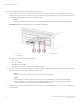


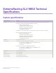
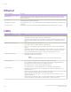
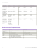
Table Of Contents
- ExtremeRouting SLX 9850-4 Hardware Installation Guide
- Preface
- About this Document
- Device Overview
- Preparing for the Installation
- Mounting the Device
- Initial Setup and Verification
- Initial setup and configuration checklist
- Items required
- Providing power to the device
- Establishing a serial connection
- Configuring a static IP address
- Establishing an Ethernet connection
- Customizing the chassis and host names
- Configuring the DNS service
- Setting the date and time
- Verifying correct operation
- Backing up the configuration
- Powering down the device
- Installing cable management kit
- Monitoring the Device
- Management Modules
- Interface Modules
- Power Supply Modules
- Power supply module overview
- Precautions specific to the power supply module
- Time and items required for removal and replacement
- Removing an AC power supply module
- Inserting an AC power supply module
- Removing a DC power supply module
- Inserting a DC power supply module
- Verifying power supply module operation
- High Voltage Power Supply Unit supporting AC and DC Voltages
- Fan Modules
- Switch Fabric Modules
- Transceivers and cables
- Supported transceivers and cables
- Time and items required
- Precautions specific to transceivers and cables
- Cleaning the fiber-optic connectors
- Managing cables
- Installing an SFP+ transceiver
- Replacing an SFP+ transceiver
- Installing a QSFP28 transceiver
- Replacing a QSFP28 transceiver
- Breakout cables
- Verifying transceiver operation
- Hardware Maintenance Schedule
- ExtremeRouting SLX 9850 Technical Specifications
- System specifications
- Ethernet
- LEDs
- Other
- Weight and physical dimensions
- Environmental requirements
- Power supply specifications (per PSU)
- Power consumption (typical configuration)
- Power consumption (maximum configuration)
- Power consumption (modules) (typical configuration)
- Power consumption (modules) (maximum configuration)
- Data port specifications (Ethernet)
- Serial port specifications (pinout RJ-45)
- Serial port specifications (protocol)
- Memory specifications
- Regulatory compliance (EMC)
- Regulatory compliance (safety)
- Regulatory compliance (environmental)
- Regulatory Statements
- Cautions and Danger Notices

System component Description
NOTE
Since the switch fabric module is behind the fan, the fan contains an LED that indicates
problems with one of the switch fabric modules behind the fan.
Other
System component Description
Serial Cable RJ-45 console cable
RJ-45 connector Uses an RJ-45 connector for the serial port
Weight and physical dimensions
"Fully loaded" SLX 9850-4 device: 144 -100 Gig port conguration with four interface modules, including two management modules,
six switch fabric modules, two fans, two power supplies, and two cable management combs.
"Fully loaded" SLX 9850-8 device: 288 - 100 Gig port conguration with eight interface modules, including two management modules,
six switch fabric modules, three fans, four power supplies, and two cable management combs.
Model Height Width Depth Weight (empty) Weight (fully loaded)
SLX 9850-4 10 rack units (RU) 43.7 cm
17.2 inches
76.2 cm
30 inches
107 lb ( 48.5 kg) Chassis without
interface modules:
212 lb (96.2 kg)
Chassis with four
SLX9850-100Gx36
CQ-M interface
modules: 283 lb
(128.4 kg)
SLX 9850-8 17 RU 43.7 cm
17.2 inches
76.2 cm
30 inches
179 lb (81.2 kg) Including chassis, 2
management
modules, 5 power
supplies, 5 switch
fabric modules, and
ller panels for the
interface modules:
359 lb (162.84 kg)
Including chassis, 2
management
modules, 5 power
supplies, 5 switch
fabric modules, and 8
SLX9850-100Gx36
CQ-M interface
modules: 503 lb
(228.16 kg)
Weight and physical dimensions
ExtremeRouting SLX 9850-4 Hardware Installation Guide
9035474-02 Rev AA 139