
Installation Guide

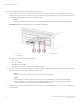


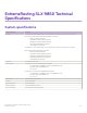
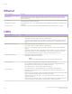
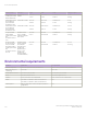
Table Of Contents
- ExtremeRouting SLX 9850-4 Hardware Installation Guide
- Preface
- About this Document
- Device Overview
- Preparing for the Installation
- Mounting the Device
- Initial Setup and Verification
- Initial setup and configuration checklist
- Items required
- Providing power to the device
- Establishing a serial connection
- Configuring a static IP address
- Establishing an Ethernet connection
- Customizing the chassis and host names
- Configuring the DNS service
- Setting the date and time
- Verifying correct operation
- Backing up the configuration
- Powering down the device
- Installing cable management kit
- Monitoring the Device
- Management Modules
- Interface Modules
- Power Supply Modules
- Power supply module overview
- Precautions specific to the power supply module
- Time and items required for removal and replacement
- Removing an AC power supply module
- Inserting an AC power supply module
- Removing a DC power supply module
- Inserting a DC power supply module
- Verifying power supply module operation
- High Voltage Power Supply Unit supporting AC and DC Voltages
- Fan Modules
- Switch Fabric Modules
- Transceivers and cables
- Supported transceivers and cables
- Time and items required
- Precautions specific to transceivers and cables
- Cleaning the fiber-optic connectors
- Managing cables
- Installing an SFP+ transceiver
- Replacing an SFP+ transceiver
- Installing a QSFP28 transceiver
- Replacing a QSFP28 transceiver
- Breakout cables
- Verifying transceiver operation
- Hardware Maintenance Schedule
- ExtremeRouting SLX 9850 Technical Specifications
- System specifications
- Ethernet
- LEDs
- Other
- Weight and physical dimensions
- Environmental requirements
- Power supply specifications (per PSU)
- Power consumption (typical configuration)
- Power consumption (maximum configuration)
- Power consumption (modules) (typical configuration)
- Power consumption (modules) (maximum configuration)
- Data port specifications (Ethernet)
- Serial port specifications (pinout RJ-45)
- Serial port specifications (protocol)
- Memory specifications
- Regulatory compliance (EMC)
- Regulatory compliance (safety)
- Regulatory compliance (environmental)
- Regulatory Statements
- Cautions and Danger Notices

ExtremeRouting SLX 9850 Technical
Specications
System specications
System component Description
Enclosure SLX 9850-4: 10 rack unit (RU) height X 17.22 inches (43.7 cm) width x 30 inches (76.2 cm) depth.
Each chassis contains the following Field-replaceable units (FRUs):
• Interface module (4 maximum)
• Switch fabric module (SFM) (6 maximum)
• Management modules (MM) (2 maximum)
• Power supply assemblies (6 maximum)
• Fan assemblies (3 maximum)
SLX 9850-8: 17 rack unit (RU) height X 17.22 inches (43.7 cm) width x 30 inches (76.2 cm) depth.
Each chassis contains the following components:
• Interface module (8 maximum)
• Switch fabric module (SFM) (6 maximum)
• Management modules (MM) (2 maximum)
• Power supply assemblies (12 maximum)
• Fan assemblies (3 maximum)
Power inlet C20; power from port side
Power supplies SLX 9850-4: Up to six hot-swappable power supplies.
• AC power supply: 2915W@200-240V or 1390W@100-120V
• DC power supply: 3000W@48V DC
• SAF-D on HV
SLX 9850-8: Up to twelve hot-swappable power supplies
• AC power supply: 2915W@200-240V or 1390W@100-120V
• DC power supply: 3000W@48V DC
• SAF-D on HV
Fan modules Three fan modules per chassis
Cooling Front-to-back airow
System architecture Non-blocking fabric
System processors 4 core, 8 thread x86 processor
Port-to-port latency <4 microseconds for 64-byte packets
ExtremeRouting SLX 9850-4 Hardware Installation Guide
9035474-02 Rev AA 137