
Brocade NetIron CES 2000 Series and NetIron CER 2000 Series
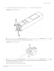
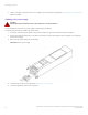
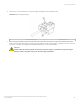
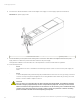
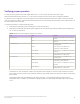
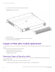
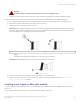
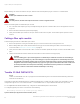
Table Of Contents
- ExtremeSwitching CES 2000 Series and ExtremeRouting CER 2000 Series Hardware Installation Guide
- Preface
- About This Document
- Product Overview
- Introduction
- Product overview
- Software features
- Upgrade applications
- Hardware features
- CES 2000 Series 2024C-4X
- CES 2000 Series 2024F-4X
- CES 2000 Series 2024C
- CES 2000 Series 2024F
- CES 2000 Series 2048C
- CES 2000 Series 2048CX
- CES 2000 Series 2048F
- CES 2000 Series 2048FX
- CER 2000 Series 2024C
- CER 2000 Series 2024F
- CER 2000 Series 2048C
- CER 2000 Series 2048CX
- CER 2000 Series 2048F
- CER 2000 Series 2048FX
- Control features
- Network interfaces
- Power supplies
- Cooling system and fans
- Connecting to a Network Device
- Installation
- Device Management Applications Familiarization
- Hardware Specifications
- Hardware Maintenance
- Hardware maintenance schedule
- Power supply replacement
- 10-Gigabit Ethernet module installation or replacement
- Replacing the fan tray
- Copper or Fiber optic module replacement
- Fiber optic connector cleaning
- Regulatory Statements
- Caution and Danger Notices

Before installing one of these modules into the port, obtain an ESD wrist strap with a plug for connection to a metal surface.
DANGER
All ber-optic interfaces use Class 1 lasers.
DANGER
For safety reasons, the ESD wrist strap should contain a series 1 megaohm resistor.
Perform the following tasks to install a ber optic module.
1. Put on the ESD wrist strap and ground yourself by attaching the clip end to a metal surface (such as an equipment rack) to act
as ground.
2. Remove the new module from its protective packaging.
3. Gently insert the ber optic module into the port until the module clicks into place. The module is keyed to prevent incorrect
insertion.
Cabling a ber optic module
Follow the steps given below to cable a
ber optic module
1. Remove the protective covering from the ber-optic port connectors and store the covering for future use.
2. Before cabling a ber optic module, Extreme Networks strongly recommends cleaning the cable connectors and the port
connectors. Refer to Fiber optic connector cleaning on page 91.
3. Gently insert the cable connectors (a tab on each connector should face upward) into the port connectors until the tabs lock into
place.
4. Observe the link and active LEDs to determine if the network connections are functioning properly.
DANGER
The intra-building port or ports of the equipment or subassembly is suitable for connection to intra-building or
unexposed wiring or cabling only. The intra-building port or ports of the equipment or subassembly MUST NOT
be metallically connected to interfaces that connect to the outside plant (OSP) or its wiring. These interfaces are
designed for use as intra-building interfaces only (Type 2 or Type 4 ports as described in GR-1089-CORE, Issue
5) and require isolation from the exposed OSP cabling. The addition of Primary Protectors is not sucient
protection in order to connect these interfaces metallically to OSP wiring.
Tunable 10 GbE DWDM SFP+
NOTE
Tunable 10 GbE DWDM SFP+ are only supported on ExtremeSwitching CES 2000 Series and ExtremeRouting CER 2000
Series 4x10G models only.
The tunable 10 GbE dense wavelength-division multiplexing (DWDM) SFP+ modular optic (part number 10G-SFPP-ZRD-T) can be
congured through the CLI to use C-band channels 1 - 102 for exible metro or campus Ethernet links that reach up to 80 km.
For 10-Gigabit Ethernet DWDM interfaces only, congure full C-band tunable optics as shown below.
To congure a physical port, enter a command such as the following.
device(config-if-e10000-1/1)# tunable-optic sfpp channel 5
Syntax: tunable-optic sfpp channel channel number [ show ]
Copper or Fiber optic module replacement
ExtremeSwitching CES 2000 Series and ExtremeRouting CER 2000 Series Hardware Installation Guide
90 53-1004198-02