
Brocade NetIron CES 2000 Series and NetIron CER 2000 Series
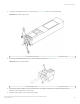
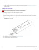
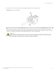
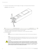
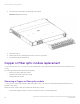
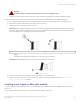
Table Of Contents
- ExtremeSwitching CES 2000 Series and ExtremeRouting CER 2000 Series Hardware Installation Guide
- Preface
- About This Document
- Product Overview
- Introduction
- Product overview
- Software features
- Upgrade applications
- Hardware features
- CES 2000 Series 2024C-4X
- CES 2000 Series 2024F-4X
- CES 2000 Series 2024C
- CES 2000 Series 2024F
- CES 2000 Series 2048C
- CES 2000 Series 2048CX
- CES 2000 Series 2048F
- CES 2000 Series 2048FX
- CER 2000 Series 2024C
- CER 2000 Series 2024F
- CER 2000 Series 2048C
- CER 2000 Series 2048CX
- CER 2000 Series 2048F
- CER 2000 Series 2048FX
- Control features
- Network interfaces
- Power supplies
- Cooling system and fans
- Connecting to a Network Device
- Installation
- Device Management Applications Familiarization
- Hardware Specifications
- Hardware Maintenance
- Hardware maintenance schedule
- Power supply replacement
- 10-Gigabit Ethernet module installation or replacement
- Replacing the fan tray
- Copper or Fiber optic module replacement
- Fiber optic connector cleaning
- Regulatory Statements
- Caution and Danger Notices

Displaying the status of the power supplies
You can display the status of the power supplies by entering the show chassis command at any level of the CLI. The display shows
whether a power supply is installed in the specied power supply slot and the status of the power supply. If you are not already attached
to a terminal or a PC running terminal emulation, see Displaying the status of the power supplies
device> show chassis
*** CES 2000 Series 2048CX ***
---POWERS ---
Power 1 ( 3I50 - AC 504W): Installed (OK)
Power 2: not present
Total power budget for system = 504 W
--- FANS ---
Metro fan tray (fan 1): Status = OK, Speed = LOW (50%)
Metro fan tray (fan 2): Status = OK, Speed = LOW (50%)
Metro fan tray (fan 3): Status = OK, Speed = LOW (50%)
Metro fan tray (fan 4): Status = OK, Speed = LOW (50%)
Metro fan tray (fan 5): Status = OK, Speed = LOW (50%)
Metro fan tray (fan 6): Status = OK, Speed = LOW (50%)
--- TEMPERATURE READINGS ---
CPU: Board 32.50C Chip 41.6C
481XG PPCR1: Board 32.50C Chip 43.31C
481XG PPCR2: Board 29.50C Chip 41.93C
2X10G PPCR: Board 33.0C Chip 41.68C
Fans are in auto mode. Temperature Monitoring Poll Period is 60 seconds
Base MAC Address = 001b.ed39.0300
CES 2000 Series 2048CX>
Syntax: show chassis
10-Gigabit Ethernet module installation or
replacement
The 2-port 10-Gigabit Ethernet modules may optionally be installed or replaced in the
eld on the CES 2000 Series 2024C, CES
2000 Series 2024F, CER 2000 Series 2024C, CER 2000 Series 2024F units. You can order the Extreme Networks device with a 2
x10-Gigabit module installed at the factory, or you can upgrade your device later.
This section provides the steps for installing, removing, and replacing the 10-Gigabit Ethernet module. You will need the following tools
to perform these procedures:
• #2 Phillips-head screwdriver
• Electrostatic Discharge (ESD) kit
DANGER
For safety reasons, the ESD wrist strap should contain a series 1 megaohm resistor.
Removing a 2 x10-Gigabit Ethernet module
Follow the procedure given below while removing a 2 x10-Gigabit Ethernet module.
1. Power o the Extreme Networks device.
2. Use a #2 Phillips-head screwdriver to loosen the screws on the 2 x10-Gigabit module.
3. Remove the 2 x10-Gigabit module.
4. Place the 2 x10-Gigabit module in an anti-static bag for storage.
5. If you are removing the module without replacing it, install the blank faceplate in the front panel.
10-Gigabit Ethernet module installation or replacement
ExtremeSwitching CES 2000 Series and ExtremeRouting CER 2000 Series Hardware Installation Guide
86 53-1004198-02