
Brocade NetIron CES 2000 Series and NetIron CER 2000 Series
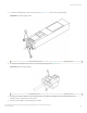
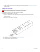
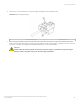
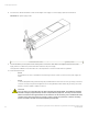
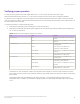
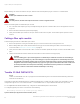
Table Of Contents
- ExtremeSwitching CES 2000 Series and ExtremeRouting CER 2000 Series Hardware Installation Guide
- Preface
- About This Document
- Product Overview
- Introduction
- Product overview
- Software features
- Upgrade applications
- Hardware features
- CES 2000 Series 2024C-4X
- CES 2000 Series 2024F-4X
- CES 2000 Series 2024C
- CES 2000 Series 2024F
- CES 2000 Series 2048C
- CES 2000 Series 2048CX
- CES 2000 Series 2048F
- CES 2000 Series 2048FX
- CER 2000 Series 2024C
- CER 2000 Series 2024F
- CER 2000 Series 2048C
- CER 2000 Series 2048CX
- CER 2000 Series 2048F
- CER 2000 Series 2048FX
- Control features
- Network interfaces
- Power supplies
- Cooling system and fans
- Connecting to a Network Device
- Installation
- Device Management Applications Familiarization
- Hardware Specifications
- Hardware Maintenance
- Hardware maintenance schedule
- Power supply replacement
- 10-Gigabit Ethernet module installation or replacement
- Replacing the fan tray
- Copper or Fiber optic module replacement
- Fiber optic connector cleaning
- Regulatory Statements
- Caution and Danger Notices

8. Secure the two chassis attachment screws near the edges of the supply to lock the supply in place (as shown below).
FIGURE 56 DC power supply screws
1 Chassis attachment screws 2 Assembly screws
9. Connect the wire to your DC power source, making sure to connect the -48V cable to the negative terminal on the power
supply and the 0V cable to the positive terminal as marked on the power supply.
The equipment installation must meet NEC/CEC code requirements. Consult local authorities for regulations.
10. Follow these precautions:
• NOTE
Ensure that the DC return is isolated from the chassis ground (DC-I) when connections to the power supply are
made.
• NOTE
To ensure adequate bonding when attaching the provided Panduit LCD6-10AF two-hole ground lug, a minimum
of 20 PSI of torque is required to be applied to the mounting hardware used to attach the ground lug. Use a star
washer to ensure an NEBS compliant connection.
• CAUTION
For a DC system, use a grounding wire of at least 6 American Wire Gauge (AWG). The 6 AWG wire should be
attached to an agency-approved crimp connector crimped with the proper tool. The crimp connector should
allow for securement to both ground screws on the enclosure. For the Ground lug, use UL listed Panduit crimp
connector, P/N LCD6-10A, and two 10-32, PPH, screws to secure crimp connector to chassis. Grounding
position is located on the side of the chassis adjacent ground symbol.
Power supply replacement
ExtremeSwitching CES 2000 Series and ExtremeRouting CER 2000 Series Hardware Installation Guide
84 53-1004198-02