
Brocade NetIron CES 2000 Series and NetIron CER 2000 Series
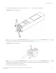
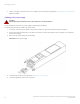
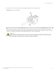
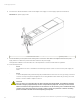
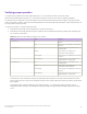
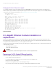
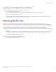
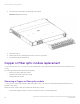
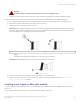
Table Of Contents
- ExtremeSwitching CES 2000 Series and ExtremeRouting CER 2000 Series Hardware Installation Guide
- Preface
- About This Document
- Product Overview
- Introduction
- Product overview
- Software features
- Upgrade applications
- Hardware features
- CES 2000 Series 2024C-4X
- CES 2000 Series 2024F-4X
- CES 2000 Series 2024C
- CES 2000 Series 2024F
- CES 2000 Series 2048C
- CES 2000 Series 2048CX
- CES 2000 Series 2048F
- CES 2000 Series 2048FX
- CER 2000 Series 2024C
- CER 2000 Series 2024F
- CER 2000 Series 2048C
- CER 2000 Series 2048CX
- CER 2000 Series 2048F
- CER 2000 Series 2048FX
- Control features
- Network interfaces
- Power supplies
- Cooling system and fans
- Connecting to a Network Device
- Installation
- Device Management Applications Familiarization
- Hardware Specifications
- Hardware Maintenance
- Hardware maintenance schedule
- Power supply replacement
- 10-Gigabit Ethernet module installation or replacement
- Replacing the fan tray
- Copper or Fiber optic module replacement
- Fiber optic connector cleaning
- Regulatory Statements
- Caution and Danger Notices

6. Insert the DC connector with wires into the power supply and tighten the two assembly screws.
FIGURE 55 The DC wiring assembly
1 Wire tightening screws 2 Assembly screws
7. With one hand, hold the bar on the front panel of the power supply. With the other hand, support the underside of the power
supply, and insert the power supply into the empty power supply slot. Press until the supply is completely in the slot, so that the
connectors on the back of the supply are fully engaged with the pins on the power backplane.
CAUTION
Carefully follow the mechanical guides on each side of the power supply slot and make sure the power supply is
properly inserted in the guides. Never insert the power supply upside down.
Power supply replacement
ExtremeSwitching CES 2000 Series and ExtremeRouting CER 2000 Series Hardware Installation Guide
53-1004198-02 83