
Brocade NetIron CES 2000 Series and NetIron CER 2000 Series
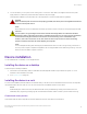
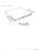
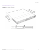
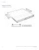
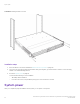
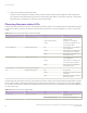
Table Of Contents
- ExtremeSwitching CES 2000 Series and ExtremeRouting CER 2000 Series Hardware Installation Guide
- Preface
- About This Document
- Product Overview
- Introduction
- Product overview
- Software features
- Upgrade applications
- Hardware features
- CES 2000 Series 2024C-4X
- CES 2000 Series 2024F-4X
- CES 2000 Series 2024C
- CES 2000 Series 2024F
- CES 2000 Series 2048C
- CES 2000 Series 2048CX
- CES 2000 Series 2048F
- CES 2000 Series 2048FX
- CER 2000 Series 2024C
- CER 2000 Series 2024F
- CER 2000 Series 2048C
- CER 2000 Series 2048CX
- CER 2000 Series 2048F
- CER 2000 Series 2048FX
- Control features
- Network interfaces
- Power supplies
- Cooling system and fans
- Connecting to a Network Device
- Installation
- Device Management Applications Familiarization
- Hardware Specifications
- Hardware Maintenance
- Hardware maintenance schedule
- Power supply replacement
- 10-Gigabit Ethernet module installation or replacement
- Replacing the fan tray
- Copper or Fiber optic module replacement
- Fiber optic connector cleaning
- Regulatory Statements
- Caution and Danger Notices

TABLE 10 LEDs for power for the 2048 models (continued)
LED Position State Meaning
Amber The fan tray is plugged in but one
or more fans are faulty.
PS1 (labeled P1) Left side of front panel O Power supply 1 is not installed or is
not providing power.
Amber Power supply 1 is installed, but not
connected or a fault is detected.
Green Power supply 1 is installed and is
functioning normally.
PS2 (labeled P2) Left side of front panel O Power supply 2 is not installed or is
not providing power.
Amber Power supply 2 is installed, but not
connected or a fault is detected.
Green Power supply 2 is installed and is
functioning normally.
DC Right side of front panel O No DC power.
Amber The following possibilities:
• The power supply has
DC power, but output is
not enabled
• The power supply is over
temperature
• The fan failed
Green Power supply has DC power, is
enabled, and has good output.
Green blinking Power supply has input power, but
DC output is not enabled.
The software regularly polls the hardware for power status information. You can display the status information from any management
session. In addition, the software automatically generates a Syslog message and SNMP trap if a status change occurs.
PC or terminal attachment
To assign an IP address, you must have access to the Command Line Interface (CLI). The CLI is a text-based interface that can be
accessed through a direct serial connection to the device and through Telnet connections.
You need to assign an IP address using the CLI. You can access the CLI by attaching a serial cable to the Console port. After you assign
an IP address, you can access the system through Telnet or Extreme Network Advisor.
Attaching a PC or terminal
Follow the steps given below to attach a management station using the serial port.
1. Connect a PC or terminal to the serial port of the system using a straight-through cable. The serial port has a male DB-9
connector.
NOTE
You need to run a terminal emulation program on the PC.
PC or terminal attachment
ExtremeSwitching CES 2000 Series and ExtremeRouting CER 2000 Series Hardware Installation Guide
53-1004198-02 59