
Brocade NetIron CES 2000 Series and NetIron CER 2000 Series
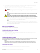
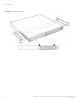
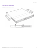
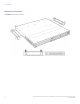
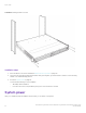
Table Of Contents
- ExtremeSwitching CES 2000 Series and ExtremeRouting CER 2000 Series Hardware Installation Guide
- Preface
- About This Document
- Product Overview
- Introduction
- Product overview
- Software features
- Upgrade applications
- Hardware features
- CES 2000 Series 2024C-4X
- CES 2000 Series 2024F-4X
- CES 2000 Series 2024C
- CES 2000 Series 2024F
- CES 2000 Series 2048C
- CES 2000 Series 2048CX
- CES 2000 Series 2048F
- CES 2000 Series 2048FX
- CER 2000 Series 2024C
- CER 2000 Series 2024F
- CER 2000 Series 2048C
- CER 2000 Series 2048CX
- CER 2000 Series 2048F
- CER 2000 Series 2048FX
- Control features
- Network interfaces
- Power supplies
- Cooling system and fans
- Connecting to a Network Device
- Installation
- Device Management Applications Familiarization
- Hardware Specifications
- Hardware Maintenance
- Hardware maintenance schedule
- Power supply replacement
- 10-Gigabit Ethernet module installation or replacement
- Replacing the fan tray
- Copper or Fiber optic module replacement
- Fiber optic connector cleaning
- Regulatory Statements
- Caution and Danger Notices

Powering on the system
1. Ensure that all power supplies are fully and properly inserted and no power supply slots are uncovered.
CAUTION
Never leave tools inside the chassis.
2. Remove the power cord from the shipping package.
3. Attach the AC power cable to the AC connector on the rear panel.
4. Insert the power cable plug into a 115V/120V outlet.
NOTE
To turn the system o, simply unplug the power
cords.
NOTE
The socket should be installed near the equipment and should be easily accessible.
NOTE
If the outlet is not rated 115/120V, stop and get the appropriate cable for the outlet.
DANGER
The intra-building port or ports of the equipment or subassembly is suitable for connection to intra-building or
unexposed wiring or cabling only. The intra-building port or ports of the equipment or subassembly MUST NOT
be metallically connected to interfaces that connect to the outside plant (OSP) or its wiring. These interfaces are
designed for use as intra-building interfaces only (Type 2 or Type 4 ports as described in GR-1089-CORE, Issue
5) and require isolation from the exposed OSP cabling. The addition of Primary Protectors is not sucient
protection in order to connect these interfaces metallically to OSP wiring.
NOTE
Before crimping the ground wire into the provided ground lug ensure the bare copper wire has been cleaned and
antioxidant is applied to the bare wire. To ensure adequate bonding when attaching the ground lug, a minimum of 20
PSI of torque is required to be applied to the mounting hardware used to attach the ground lug.
Operation verication
After you have installed any redundant power supplies, verify that the device is working properly by plugging it into a power source and
verifying that it passes its self test.
If your device has more than one power supply installed, repeat this procedure for each power supply.
Verifying proper operation
1. Connect the power cord supplied with the device to the power connector on the power supply on the rear of the device.
2. Insert the other end into a properly grounded electrical outlet.
3. Verify that the LED for each power supply is a solid green.
Operation verication
ExtremeSwitching CES 2000 Series and ExtremeRouting CER 2000 Series Hardware Installation Guide
53-1004198-02 57