
Brocade NetIron CES 2000 Series and NetIron CER 2000 Series
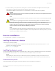
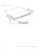
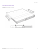
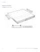
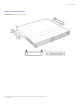
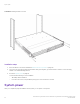
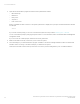
Table Of Contents
- ExtremeSwitching CES 2000 Series and ExtremeRouting CER 2000 Series Hardware Installation Guide
- Preface
- About This Document
- Product Overview
- Introduction
- Product overview
- Software features
- Upgrade applications
- Hardware features
- CES 2000 Series 2024C-4X
- CES 2000 Series 2024F-4X
- CES 2000 Series 2024C
- CES 2000 Series 2024F
- CES 2000 Series 2048C
- CES 2000 Series 2048CX
- CES 2000 Series 2048F
- CES 2000 Series 2048FX
- CER 2000 Series 2024C
- CER 2000 Series 2024F
- CER 2000 Series 2048C
- CER 2000 Series 2048CX
- CER 2000 Series 2048F
- CER 2000 Series 2048FX
- Control features
- Network interfaces
- Power supplies
- Cooling system and fans
- Connecting to a Network Device
- Installation
- Device Management Applications Familiarization
- Hardware Specifications
- Hardware Maintenance
- Hardware maintenance schedule
- Power supply replacement
- 10-Gigabit Ethernet module installation or replacement
- Replacing the fan tray
- Copper or Fiber optic module replacement
- Fiber optic connector cleaning
- Regulatory Statements
- Caution and Danger Notices

FIGURE 45 Installing the device in a rack
Installation steps
1. Mount the device in the rack as illustrated in Reverse rack mount position on page 55.
2. Using a 2-hole grounding lug and a minimum #6 AWG grounding wire, ground the chassis to either a common bonding
network or an isolated bonding network.
3. Proceed to System power on page 56.
You will need the following tools for installation:
• #2 Phillips-head screwdriver
• Four #10-24 screws (or as specied by rack type) to mount the device to the rack
System power
After you complete the physical installation of the system, you can power on the system.
System power
ExtremeSwitching CES 2000 Series and ExtremeRouting CER 2000 Series Hardware Installation Guide
56 53-1004198-02