
Brocade NetIron CES 2000 Series and NetIron CER 2000 Series
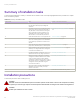

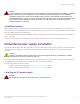
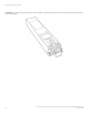
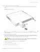
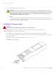
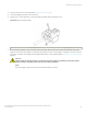
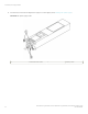
Table Of Contents
- ExtremeSwitching CES 2000 Series and ExtremeRouting CER 2000 Series Hardware Installation Guide
- Preface
- About This Document
- Product Overview
- Introduction
- Product overview
- Software features
- Upgrade applications
- Hardware features
- CES 2000 Series 2024C-4X
- CES 2000 Series 2024F-4X
- CES 2000 Series 2024C
- CES 2000 Series 2024F
- CES 2000 Series 2048C
- CES 2000 Series 2048CX
- CES 2000 Series 2048F
- CES 2000 Series 2048FX
- CER 2000 Series 2024C
- CER 2000 Series 2024F
- CER 2000 Series 2048C
- CER 2000 Series 2048CX
- CER 2000 Series 2048F
- CER 2000 Series 2048FX
- Control features
- Network interfaces
- Power supplies
- Cooling system and fans
- Connecting to a Network Device
- Installation
- Device Management Applications Familiarization
- Hardware Specifications
- Hardware Maintenance
- Hardware maintenance schedule
- Power supply replacement
- 10-Gigabit Ethernet module installation or replacement
- Replacing the fan tray
- Copper or Fiber optic module replacement
- Fiber optic connector cleaning
- Regulatory Statements
- Caution and Danger Notices

9. Connect the plug end of the power cord into outlet.
CAUTION
For an Extreme Networks AC system, use a ground wire of at least 6 American Wire Gauge (AWG). The ground
wire should have an agency-approved crimped connector (provided with the chassis) attached to one end, with the
other end attached to building ground. The connector must be crimped with the proper tool, allowing it to be
connected to both ground screws on the enclosure.
NOTE
To insure adequate bonding when attaching the provided Panduit LCD6-10AF two-hole ground lug, a minimum of
20 inch pounds of torque is required to be applied to the mounting hardware used to attach the ground lug. Use a star
washer to ensure an NEBS compliant connection.
Installing a DC power supply
DANGER
Before beginning the installation, see the precautions in “Power precautions.”
Use the following procedures for DC power supplies in CES 2000 Series, CER 2000 Series 2000 series devices.
Follow the steps given below to install an DC power supply.
1. If necessary, remove the power supply locking screws located in the upper left and the bottom right of the device.
2. If the empty power supply bay has a cover plate, remove the two screws near the edges of the cover plate to unlock the plate,
then remove the plate.
3. Remove the DC power supply from its packaging (Installing a DC power supply).
FIGURE 38 The DC power supply
Redundant power supply installation
ExtremeSwitching CES 2000 Series and ExtremeRouting CER 2000 Series Hardware Installation Guide
48 53-1004198-02