
Brocade NetIron CES 2000 Series and NetIron CER 2000 Series
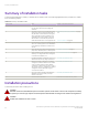

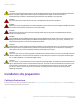
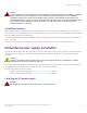
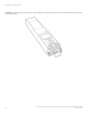
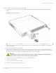
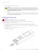
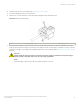
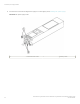
Table Of Contents
- ExtremeSwitching CES 2000 Series and ExtremeRouting CER 2000 Series Hardware Installation Guide
- Preface
- About This Document
- Product Overview
- Introduction
- Product overview
- Software features
- Upgrade applications
- Hardware features
- CES 2000 Series 2024C-4X
- CES 2000 Series 2024F-4X
- CES 2000 Series 2024C
- CES 2000 Series 2024F
- CES 2000 Series 2048C
- CES 2000 Series 2048CX
- CES 2000 Series 2048F
- CES 2000 Series 2048FX
- CER 2000 Series 2024C
- CER 2000 Series 2024F
- CER 2000 Series 2048C
- CER 2000 Series 2048CX
- CER 2000 Series 2048F
- CER 2000 Series 2048FX
- Control features
- Network interfaces
- Power supplies
- Cooling system and fans
- Connecting to a Network Device
- Installation
- Device Management Applications Familiarization
- Hardware Specifications
- Hardware Maintenance
- Hardware maintenance schedule
- Power supply replacement
- 10-Gigabit Ethernet module installation or replacement
- Replacing the fan tray
- Copper or Fiber optic module replacement
- Fiber optic connector cleaning
- Regulatory Statements
- Caution and Danger Notices

Installation
• System unpacking.............................................................................................................................................................................................41
• Summary of installation tasks.......................................................................................................................................................................42
• Installation precautions....................................................................................................................................................................................42
• Installation site preparation............................................................................................................................................................................ 44
• Redundant power supply installation.........................................................................................................................................................45
• Device installation..............................................................................................................................................................................................51
• System power..................................................................................................................................................................................................... 56
• Operation verication.......................................................................................................................................................................................57
• PC or terminal attachment.............................................................................................................................................................................59
System unpacking
DANGER
The procedures in this manual are for qualied service personnel.
The Extreme systems ship with all of the following items. Please review the list below and verify the contents. If any items are missing,
please contact the place of purchase.
Package contents
The package contains the following:
• ExtremeSwitching CES 2000 Series or ExtremeRouting CER 2000 Series device
• 115V AC power cable (for AC sourced devices)
General requirements
To manage the system, you need the following items for serial connection to the router:
• A management station, such as a PC running a terminal emulation application.
• A straight-through EIA/TIA DB-9 serial cable (F/F). The serial cable can be ordered separately from Extreme Networks. If you
prefer to build your own cable, refer to the pinout information in General requirements.
You use the serial connection to perform basic
conguration tasks including assigning an IP address and network mask to the system.
This information is required for managing the system using Extreme Network Advisor or using the CLI through Telnet.
CAUTION
To prevent damage to the chassis and components, never attempt to lift the chassis using the fan or power supply handles.
These handles were not designed to support the weight of the chassis.
CAUTION
Before plugging a cable into any port, be sure to discharge the voltage stored on the cable by touching the electrical
contacts to ground surface.
ExtremeSwitching CES 2000 Series and ExtremeRouting CER 2000 Series Hardware Installation Guide
53-1004198-02 41