
Installation Guide


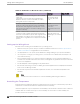


Table Of Contents
- Table of Contents
- Preface
- ExtremeSwitching Switches
- Overview of the Switches
- ExtremeSwitching X435 Series Switches
- ExtremeSwitching X440-G2 Series Switches
- ExtremeSwitching X440-G2-12t-10GE4 Switch Ports and Slots
- ExtremeSwitching X440-G2-12p-10GE4 Switch Ports and Slots
- ExtremeSwitching X440-G2-24t-10GE4 Switch Ports and Slots
- ExtremeSwitching X440-G2-24x-10GE4 Switch Ports and Slots
- ExtremeSwitching X440-G2-24p-10GE4 Switch Ports and Slots
- ExtremeSwitching X440-G2-48t-10GE4 Switch Ports and Slots
- ExtremeSwitching X440-G2-48p-10GE4 Switch Ports and Slots
- ExtremeSwitching X440-G2-24t-10GE4-DC Switch Ports and Slots
- ExtremeSwitching X440-G2-48t-10GE4-DC Switch Ports and Slots
- ExtremeSwitching X440-G2-12t8fx-GE4 Switch Ports and Slots
- ExtremeSwitching X440-G2-24fx-GE4 Switch Ports and Slots
- ExtremeSwitching X440-G2-24t-GE4 Switch Ports and Slots
- ExtremeSwitching X440-G2 Series Switch LEDs
- ExtremeSwitching X450-G2 Series Switches
- ExtremeSwitching X450-G2-24t-GE4 Switch Ports and Slots
- ExtremeSwitching X450-G2-24t-10GE4 Switch Ports and Slots
- ExtremeSwitching X450-G2-48t-GE4 Switch Ports and Slots
- ExtremeSwitching X450-G2-48t-10GE4 Switch Ports and Slots
- ExtremeSwitching X450-G2-24p-GE4 Switch Ports and Slots
- ExtremeSwitching X450-G2-24p-10GE4 Switch Ports and Slots
- ExtremeSwitching X450-G2-48p-GE4 Switch Ports and Slots
- ExtremeSwitching X450-G2-48p-10GE4 Switch Ports and Slots
- ExtremeSwitching X450-G2 Series Switch LEDs
- ExtremeSwitching X460-G2 Series Switches
- ExtremeSwitching X460-G2-24t-GE4 Switch Ports and Slots
- ExtremeSwitching X460-G2-24t-10GE4 Switch Ports and Slots
- ExtremeSwitching X460-G2-24x-10GE4 Switch Ports and Slots
- ExtremeSwitching X460-G2-24p-GE4 Switch Ports and Slots
- ExtremeSwitching X460-G2-24p-10GE4 Switch Ports and Slots
- ExtremeSwitching X460-G2-48t-GE4 Switch Ports and Slots
- ExtremeSwitching X460-G2-48t-10GE4 Switch Ports and Slots
- ExtremeSwitching X460-G2-24t-24ht-10GE4 Switch Ports and Slots
- ExtremeSwitching X460-G2-48x-10GE4 Switch Ports and Slots
- Summit X460-G2-48p-GE4 Switch Ports and Slots
- ExtremeSwitching X460-G2-48p-10GE4 Switch Ports and Slots
- ExtremeSwitching X460-G2-24p-24hp-10GE4 Switch Ports and Slots
- ExtremeSwitching X460-G2-16mp-32p-10GE4 Switch Ports and Slots
- ExtremeSwitching X460-G2 Series Switch LEDs
- ExtremeSwitching X465 Series Switches
- ExtremeSwitching X465-24MU Switch Ports and Slots
- ExtremeSwitching X465-24MU-24W Switch Ports and Slots
- ExtremeSwitching X465-24S Switch Ports and Slots
- ExtremeSwitching X465-24W Switch Ports and Slots
- ExtremeSwitching X465-24XE Switch Ports and Slots
- ExtremeSwitching X465-48P Switch Ports and Slots
- ExtremeSwitching X465-48T Switch Ports and Slots
- ExtremeSwitching X465-48W Switch Ports and Slots
- ExtremeSwitching X465i-48W Switch Ports and Slots
- ExtremeSwitching X465 Series Switch LEDs
- ExtremeSwitching X590 Series Switches
- ExtremeSwitching X620 Series Switches
- ExtremeSwitching X670-G2 Series Switches
- ExtremeSwitching X690 Series Switches
- ExtremeSwitching X695 Switch
- ExtremeSwitching X870 Series Switches
- Pluggable Interfaces for the Switches
- Power Supplies for Use with Your Switch
- External Power Supplies
- Replaceable Internal Power Supplies
- Summit 300 W AC and DC Power Supplies
- Summit 350 W AC Power Supplies
- Summit 550 W AC and DC Power Supplies
- Summit 715 W AC Power Supplies
- Summit 750 W AC Power Supply
- 750 W AC and DC Power Supplies
- Summit 770 W AC Power Supplies
- Summit 1100 W AC Power Supplies
- Summit 1100 W DC Power Supplies
- ExtremeSwitching 2000 W AC Power Supply
- Displaying the Status of Installed Power Supplies
- Expansion Modules
- Site Preparation
- Building Stacks
- Introduction to Stacking
- Plan to Create Your Stack
- Enabling and Disabling the Stacking-Support Option
- Recommendations for Placing Switches for Stacked Operation
- Recommendations for Configuring Stacks
- Stacking Considerations for Each Switch Model
- Selecting Native and Alternate Stacking Ports
- Combining Switches from Different Series
- Selecting Stacking Cables
- Using the Extreme Stacking Tool
- Set up the Physical Stack
- Installing Your Extreme Networks Switch
- Safety Considerations for Installing Switches
- Pre-installation Requirements
- Attaching the Switch to a Rack or Cabinet
- Installing Optional Components
- Installing Internal Power Supplies
- Install a 300 W Internal DC Power Supply
- Install a 450 W or 550 W Internal DC Power Supply
- Required Tools and Materials for Installing a 450 W or 550 W DC Power Supply
- Preparing the Cables for a 450 W or 550 W DC Power Supply
- Installing a 450 W or 550 W DC Power Supply
- Connecting the Ground Wire to a 450 W or 550 W DC Power Supply
- Connecting a 450 W or 550 W DC Power Supply to the Source Voltage
- Installing a 750 W Internal DC Power Supply
- Install an 1100 W Internal DC Power Supply
- Installing Internal AC Power Supplies
- Connecting Power to the Switch
- Connect Network Interface Cables
- Performing Initial Management Tasks
- Installing External Power Supplies
- Safety Considerations for Installing Power Supplies
- Pre-installation Requirements
- Installing an EPS-C2 Power Supply
- Installing an RPS-150XT Redundant Power Supply
- Installing an RPS-500p Redundant Power Supply
- Installing an STK-RPS-150PS Redundant Power Supply
- Installing an STK-RPS-1005PS Redundant Power Supply
- Installing a VX-RPS-1000 Redundant Power Supply
- Installing Expansion Modules
- Installing a V300 Virtual Port Extender
- Install a V300 Virtual Port Extender on a Wall
- Install a V300 Virtual Port Extender Under or on a Table Surface
- Install a V300 Virtual Port Extender in a VESA Mount
- Install a V300 in a Single Rack Mount
- Install a V300 in a Dual Rack Mount
- Install a V300 in a DIN Rail Mount
- Install a V300-8P-2T-W Model in a Single or Dual Rack Mount
- Installing a V300-8P-2T-W Model in a DIN Rail Mount
- Connecting the V300 Virtual Port Extender to Power
- Installing a V400 Virtual Port Extender
- Installing an LRM/MACsec Adapter
- Installing a Half-Duplex to Full-Duplex Converter
- Installing a Versatile Interface Module or Clock Module in an X460-G2 Series Switch
- Installing a Versatile Interface Module in an X465 Series Switch
- Install an SSD Module
- Installing a V300 Virtual Port Extender
- Replacing AC Power Supplies
- Replacing a Summit 300 W AC Power Supply
- Replacing a Summit 350 W or 715 W AC Power Supply
- Replacing a Summit 450 W or 550 W AC Power Supply
- Replacing a 750 W AC Power Supply
- Replacing a Summit 770 W AC Power Supply
- Replacing a Summit 1100 W AC Power Supply
- Replacing an ExtremeSwitching 2000 W AC Power Supply
- Removing an RPS-150XT Redundant Power Supply
- Removing an RPS-500p Redundant Power Supply
- Removing an STK-RPS-150PS Redundant Power Supply
- Removing an STK-RPS-1005PS Redundant Power Supply
- Removing a VX-RPS-1000 Redundant Power Supply
- Replacing DC Power Supplies
- Replacing Fan Modules
- Removing and Replacing Expansion Modules
- Removing or Replacing a V300 Virtual Port Extender
- Removing or Replacing a V400 Virtual Port Extender
- Removing or Replacing an LRM/MACsec Adapter
- Removing or Replacing a Half-Duplex to Full-Duplex Converter
- Replacing a Versatile Interface Module, Solid-state Drive, or Clock Module in an X460-G2 Series or X465 Series Switch
- Removing Switches from Service
- Technical Specifications
- ExtremeSwitching X435 Series Switches Technical Specifications
- ExtremeSwitching X440-G2 Series Switches Technical Specifications
- ExtremeSwitching X450-G2 Series Switches Technical Specifications
- ExtremeSwitching X460-G2 Series Switches Technical Specifications
- ExtremeSwitching X465 Series Switches Technical Specifications
- ExtremeSwitching X590 Series Switches Technical Specifications
- ExtremeSwitching X620 Series Switches Technical Specifications
- Summit X670-G2 Series Switches Technical Specifications
- ExtremeSwitching X690 Series Switches Technical Specifications
- ExtremeSwitching X695 Series Switch Technical Specifications
- ExtremeSwitching X870 Series Switches Technical Specifications
- V300 Virtual Port Extender Specifications
- V400 Virtual Port Extender Technical Specifications
- LRM/MACsec Adapter Technical Specifications
- Half-Duplex to Full-Duplex Converter Technical Specifications
- Summit 300 W Power Supplies Technical Specifications
- Summit 350 W Power Supplies Technical Specifications
- Summit 550 W Power Supplies Technical Specifications
- Summit 715 W Power Supplies Technical Specifications
- 750 W Power Supplies Technical Specifications
- 750 W Power Supplies Technical Specifications
- Summit 770 W Power Supplies Technical Specifications
- Summit 1100 W Power Supplies Technical Specifications
- ExtremeSwitching 2000 W Power Supply Technical Specifications
- EPS-C2 Redundant Power Supply Technical Specifications
- RPS-90 Redundant Power Supply Technical Specifications
- RPS-150XT Redundant Power Supply Technical Specifications
- RPS-500p Redundant Power Supply Technical Specifications
- STK-RPS-150PS and RPS Shelves Technical Specifications
- STK-RPS-1005PS Redundant Power Supply Technical Specifications
- VX-RPS-1000 Redundant Power Supply Technical Specifications
- 3-Slot Modular Shelves: Technical Specifications
- Power Cord Requirements for AC-Powered Switches and AC Power Supplies
- Console Connector Pinouts
- Safety and Regulatory Information
- Considerations Before Installing
- General Safety Precautions
- Maintenance Safety
- Fiber Optic Ports and Optical Safety
- Cable Routing for LAN Systems
- Installing Power Supply Units and Connecting Power
- Selecting Power Supply Cords
- Battery Notice
- Battery Warning - Taiwan
- EMC Warnings
- Japan (VCCI Class A)
- Korea EMC Statement
- Index

Observe these additional thermal recommendations for the location where you plan to install your
equipment:
• Ensure that the ventilation in the wiring closet is adequate to maintain a temperature below 40°C
(104°F).
• Install a reliable air conditioning and ventilation system.
• Keep the ventilation in the wiring closet running during non-business hours; otherwise, the
equipment can overheat.
• Maintain a storage temperature between -40°C (-40°F) and 70°C (158°F).
Table 71 on page 167 summarizes the behavior of ExtremeSwitching switches when they experience
high operating temperatures.
Table 72 on page 167 lists the ambient temperature range for ExtremeSwitching switches. As with all
electrical equipment, however, Extreme Networks product lifetimes degrade with increased
temperature. Ideally, therefore, temperatures should be kept at or below 25°C (77°F).
Safeguards are built into all Extreme Networks switches and power supply units to minimize the risk of
fire.
Table 71: Thermal Shutdown and Restart Behavior
Switch Model(s) Behavior
All models except
those listed below
When internal system temperatures exceed the thermal shutdown temperature
limit (typically about 20°C higher than normal system operating temperatures),
the system’s power supplies are turned o and the switch shuts down. The
system remains in the OFF state until the system has sucient time to cool and
the internal thermal sensor measures a temperature lower than the maximum
specified ambient temperature, at which time the system restarts automatically.
Alternately, you can restart the system immediately by removing and then
restoring all line power to the system.
X460-G2
(all models)
When internal system temperatures exceed the thermal shutdown temperature
limit (typically about 20°C higher than normal system operating temperatures),
the system’s power supplies are turned o and the switch shuts down. The switch
does not restart automatically, even after cooling. It remains in the OFF state until
you remove and then restore all line power to the system.
Table 72: Ambient Temperature Range for Switches
Switch Series Ambient Operating Temperature Range
X440-G2 0°C (32°F) to 50°C (122°F)
Note: The maximum temperature is 60°C (140°F) for the following models: X440-
G2-12t8fx-GE4, X440-G2-24fx-GE4, X440-G2-24t-GE4.
X450-G2 0°C (32°F) to 50°C (122°F)
X460-G2 0°C (32°F) to 50°C (122°F)
X590 0°C (32°F) to 45°C (113°F)
X620 0°C (32°F) to 50°C (122°F)
X670-G2 0°C (32°F) to 45°C (113°F)
Site Preparation Controlling the Temperature
ExtremeSwitching Hardware Installation Guide 167