
Installation Guide

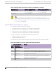


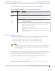


Table Of Contents
- Table of Contents
- Preface
- ExtremeSwitching Switches
- Overview of the Switches
- ExtremeSwitching X435 Series Switches
- ExtremeSwitching X440-G2 Series Switches
- ExtremeSwitching X440-G2-12t-10GE4 Switch Ports and Slots
- ExtremeSwitching X440-G2-12p-10GE4 Switch Ports and Slots
- ExtremeSwitching X440-G2-24t-10GE4 Switch Ports and Slots
- ExtremeSwitching X440-G2-24x-10GE4 Switch Ports and Slots
- ExtremeSwitching X440-G2-24p-10GE4 Switch Ports and Slots
- ExtremeSwitching X440-G2-48t-10GE4 Switch Ports and Slots
- ExtremeSwitching X440-G2-48p-10GE4 Switch Ports and Slots
- ExtremeSwitching X440-G2-24t-10GE4-DC Switch Ports and Slots
- ExtremeSwitching X440-G2-48t-10GE4-DC Switch Ports and Slots
- ExtremeSwitching X440-G2-12t8fx-GE4 Switch Ports and Slots
- ExtremeSwitching X440-G2-24fx-GE4 Switch Ports and Slots
- ExtremeSwitching X440-G2-24t-GE4 Switch Ports and Slots
- ExtremeSwitching X440-G2 Series Switch LEDs
- ExtremeSwitching X450-G2 Series Switches
- ExtremeSwitching X450-G2-24t-GE4 Switch Ports and Slots
- ExtremeSwitching X450-G2-24t-10GE4 Switch Ports and Slots
- ExtremeSwitching X450-G2-48t-GE4 Switch Ports and Slots
- ExtremeSwitching X450-G2-48t-10GE4 Switch Ports and Slots
- ExtremeSwitching X450-G2-24p-GE4 Switch Ports and Slots
- ExtremeSwitching X450-G2-24p-10GE4 Switch Ports and Slots
- ExtremeSwitching X450-G2-48p-GE4 Switch Ports and Slots
- ExtremeSwitching X450-G2-48p-10GE4 Switch Ports and Slots
- ExtremeSwitching X450-G2 Series Switch LEDs
- ExtremeSwitching X460-G2 Series Switches
- ExtremeSwitching X460-G2-24t-GE4 Switch Ports and Slots
- ExtremeSwitching X460-G2-24t-10GE4 Switch Ports and Slots
- ExtremeSwitching X460-G2-24x-10GE4 Switch Ports and Slots
- ExtremeSwitching X460-G2-24p-GE4 Switch Ports and Slots
- ExtremeSwitching X460-G2-24p-10GE4 Switch Ports and Slots
- ExtremeSwitching X460-G2-48t-GE4 Switch Ports and Slots
- ExtremeSwitching X460-G2-48t-10GE4 Switch Ports and Slots
- ExtremeSwitching X460-G2-24t-24ht-10GE4 Switch Ports and Slots
- ExtremeSwitching X460-G2-48x-10GE4 Switch Ports and Slots
- Summit X460-G2-48p-GE4 Switch Ports and Slots
- ExtremeSwitching X460-G2-48p-10GE4 Switch Ports and Slots
- ExtremeSwitching X460-G2-24p-24hp-10GE4 Switch Ports and Slots
- ExtremeSwitching X460-G2-16mp-32p-10GE4 Switch Ports and Slots
- ExtremeSwitching X460-G2 Series Switch LEDs
- ExtremeSwitching X465 Series Switches
- ExtremeSwitching X465-24MU Switch Ports and Slots
- ExtremeSwitching X465-24MU-24W Switch Ports and Slots
- ExtremeSwitching X465-24S Switch Ports and Slots
- ExtremeSwitching X465-24W Switch Ports and Slots
- ExtremeSwitching X465-24XE Switch Ports and Slots
- ExtremeSwitching X465-48P Switch Ports and Slots
- ExtremeSwitching X465-48T Switch Ports and Slots
- ExtremeSwitching X465-48W Switch Ports and Slots
- ExtremeSwitching X465i-48W Switch Ports and Slots
- ExtremeSwitching X465 Series Switch LEDs
- ExtremeSwitching X590 Series Switches
- ExtremeSwitching X620 Series Switches
- ExtremeSwitching X670-G2 Series Switches
- ExtremeSwitching X690 Series Switches
- ExtremeSwitching X695 Switch
- ExtremeSwitching X870 Series Switches
- Pluggable Interfaces for the Switches
- Power Supplies for Use with Your Switch
- External Power Supplies
- Replaceable Internal Power Supplies
- Summit 300 W AC and DC Power Supplies
- Summit 350 W AC Power Supplies
- Summit 550 W AC and DC Power Supplies
- Summit 715 W AC Power Supplies
- Summit 750 W AC Power Supply
- 750 W AC and DC Power Supplies
- Summit 770 W AC Power Supplies
- Summit 1100 W AC Power Supplies
- Summit 1100 W DC Power Supplies
- ExtremeSwitching 2000 W AC Power Supply
- Displaying the Status of Installed Power Supplies
- Expansion Modules
- Site Preparation
- Building Stacks
- Introduction to Stacking
- Plan to Create Your Stack
- Enabling and Disabling the Stacking-Support Option
- Recommendations for Placing Switches for Stacked Operation
- Recommendations for Configuring Stacks
- Stacking Considerations for Each Switch Model
- Selecting Native and Alternate Stacking Ports
- Combining Switches from Different Series
- Selecting Stacking Cables
- Using the Extreme Stacking Tool
- Set up the Physical Stack
- Installing Your Extreme Networks Switch
- Safety Considerations for Installing Switches
- Pre-installation Requirements
- Attaching the Switch to a Rack or Cabinet
- Installing Optional Components
- Installing Internal Power Supplies
- Install a 300 W Internal DC Power Supply
- Install a 450 W or 550 W Internal DC Power Supply
- Required Tools and Materials for Installing a 450 W or 550 W DC Power Supply
- Preparing the Cables for a 450 W or 550 W DC Power Supply
- Installing a 450 W or 550 W DC Power Supply
- Connecting the Ground Wire to a 450 W or 550 W DC Power Supply
- Connecting a 450 W or 550 W DC Power Supply to the Source Voltage
- Installing a 750 W Internal DC Power Supply
- Install an 1100 W Internal DC Power Supply
- Installing Internal AC Power Supplies
- Connecting Power to the Switch
- Connect Network Interface Cables
- Performing Initial Management Tasks
- Installing External Power Supplies
- Safety Considerations for Installing Power Supplies
- Pre-installation Requirements
- Installing an EPS-C2 Power Supply
- Installing an RPS-150XT Redundant Power Supply
- Installing an RPS-500p Redundant Power Supply
- Installing an STK-RPS-150PS Redundant Power Supply
- Installing an STK-RPS-1005PS Redundant Power Supply
- Installing a VX-RPS-1000 Redundant Power Supply
- Installing Expansion Modules
- Installing a V300 Virtual Port Extender
- Install a V300 Virtual Port Extender on a Wall
- Install a V300 Virtual Port Extender Under or on a Table Surface
- Install a V300 Virtual Port Extender in a VESA Mount
- Install a V300 in a Single Rack Mount
- Install a V300 in a Dual Rack Mount
- Install a V300 in a DIN Rail Mount
- Install a V300-8P-2T-W Model in a Single or Dual Rack Mount
- Installing a V300-8P-2T-W Model in a DIN Rail Mount
- Connecting the V300 Virtual Port Extender to Power
- Installing a V400 Virtual Port Extender
- Installing an LRM/MACsec Adapter
- Installing a Half-Duplex to Full-Duplex Converter
- Installing a Versatile Interface Module or Clock Module in an X460-G2 Series Switch
- Installing a Versatile Interface Module in an X465 Series Switch
- Install an SSD Module
- Installing a V300 Virtual Port Extender
- Replacing AC Power Supplies
- Replacing a Summit 300 W AC Power Supply
- Replacing a Summit 350 W or 715 W AC Power Supply
- Replacing a Summit 450 W or 550 W AC Power Supply
- Replacing a 750 W AC Power Supply
- Replacing a Summit 770 W AC Power Supply
- Replacing a Summit 1100 W AC Power Supply
- Replacing an ExtremeSwitching 2000 W AC Power Supply
- Removing an RPS-150XT Redundant Power Supply
- Removing an RPS-500p Redundant Power Supply
- Removing an STK-RPS-150PS Redundant Power Supply
- Removing an STK-RPS-1005PS Redundant Power Supply
- Removing a VX-RPS-1000 Redundant Power Supply
- Replacing DC Power Supplies
- Replacing Fan Modules
- Removing and Replacing Expansion Modules
- Removing or Replacing a V300 Virtual Port Extender
- Removing or Replacing a V400 Virtual Port Extender
- Removing or Replacing an LRM/MACsec Adapter
- Removing or Replacing a Half-Duplex to Full-Duplex Converter
- Replacing a Versatile Interface Module, Solid-state Drive, or Clock Module in an X460-G2 Series or X465 Series Switch
- Removing Switches from Service
- Technical Specifications
- ExtremeSwitching X435 Series Switches Technical Specifications
- ExtremeSwitching X440-G2 Series Switches Technical Specifications
- ExtremeSwitching X450-G2 Series Switches Technical Specifications
- ExtremeSwitching X460-G2 Series Switches Technical Specifications
- ExtremeSwitching X465 Series Switches Technical Specifications
- ExtremeSwitching X590 Series Switches Technical Specifications
- ExtremeSwitching X620 Series Switches Technical Specifications
- Summit X670-G2 Series Switches Technical Specifications
- ExtremeSwitching X690 Series Switches Technical Specifications
- ExtremeSwitching X695 Series Switch Technical Specifications
- ExtremeSwitching X870 Series Switches Technical Specifications
- V300 Virtual Port Extender Specifications
- V400 Virtual Port Extender Technical Specifications
- LRM/MACsec Adapter Technical Specifications
- Half-Duplex to Full-Duplex Converter Technical Specifications
- Summit 300 W Power Supplies Technical Specifications
- Summit 350 W Power Supplies Technical Specifications
- Summit 550 W Power Supplies Technical Specifications
- Summit 715 W Power Supplies Technical Specifications
- 750 W Power Supplies Technical Specifications
- 750 W Power Supplies Technical Specifications
- Summit 770 W Power Supplies Technical Specifications
- Summit 1100 W Power Supplies Technical Specifications
- ExtremeSwitching 2000 W Power Supply Technical Specifications
- EPS-C2 Redundant Power Supply Technical Specifications
- RPS-90 Redundant Power Supply Technical Specifications
- RPS-150XT Redundant Power Supply Technical Specifications
- RPS-500p Redundant Power Supply Technical Specifications
- STK-RPS-150PS and RPS Shelves Technical Specifications
- STK-RPS-1005PS Redundant Power Supply Technical Specifications
- VX-RPS-1000 Redundant Power Supply Technical Specifications
- 3-Slot Modular Shelves: Technical Specifications
- Power Cord Requirements for AC-Powered Switches and AC Power Supplies
- Console Connector Pinouts
- Safety and Regulatory Information
- Considerations Before Installing
- General Safety Precautions
- Maintenance Safety
- Fiber Optic Ports and Optical Safety
- Cable Routing for LAN Systems
- Installing Power Supply Units and Connecting Power
- Selecting Power Supply Cords
- Battery Notice
- Battery Warning - Taiwan
- EMC Warnings
- Japan (VCCI Class A)
- Korea EMC Statement
- Index

The Summit 750 W AC power supply has the status LEDs listed in the following table.
Table 52: Summit 750 W AC Power Supply LED Status Indications
Label and Color State Meaning
AC OK
Green
O No AC input
On AC input is good.
DC OK
Green
O Both DC outputs (55 V and 12 V) are bad or not enabled.
Blinking One output is enabled and good; the second output is bad or not
enabled.
On Both the 55 V and 12 V outputs are enabled and good.
ALM
Red
O No fault condition exists.
Blinking Power supply alert: power supply is likely to fail because of a developing
fault, such as abnormal thermal conditions or poor fan performance.
or
One output (55 V or 12 V) is bad.
On Both outputs (55 V and 12 V) are bad.
Power supply is receiving 3.3 VSB from the system. (AC OK and DC OK
are o.)
Thermal shutdown, fan failure, or any fault condition when both 55 V and
12 V are turned OFF.
750 W AC and DC Power Supplies
750 W power supplies are available for the ExtremeSwitching X695 switch in the following models:
• 750W AC power supply - front-to-back airflow (part no. XN-ACPWR-750W-F)
• 750W AC power supply - back-to-front airflow (part no. XN-ACPWR-750W-R)
• 750W DC power supply - front-to-back airflow (part no. XN-DCPWR-750W-F)
• 750W DC power supply - back-to-front airflow (part no. XN-DCPWR-750W-R)
Note
AC power input cords are not provided with AC power supplies. You can order an appropriate
cord from Extreme Networks or from your local supplier. The power cord must meet the
requirements listed in Power Cord Requirements for AC-Powered Switches and AC Power
Supplies on page 476.
The power supply must have the same airflow direction (front-to-back or back-to-front) as the switch
with which it is being used. In a redundant power configuration, the airflow direction must be the same
for both power supplies, and it must match the airflow direction of the fans in the switch.
For information on installing or replacing an AC or DC power supply, see the following topics:
• Install a 300 W or 750 W Internal AC Power Supply on page 252
• Install a 750 W DC Power Supply on page 243
The following tables describe the meanings of the LEDs on the 750 W AC power supply (part number
XN-ACPWR-750W-F or XN-ACPWR-750W-R).
Power Supplies for Use with Your Switch
750 W AC and DC Power Supplies
ExtremeSwitching Hardware Installation Guide 135