
Installation Guide
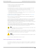


Table Of Contents
- Table of Contents
- Preface
- ExtremeSwitching Switches
- Overview of the Switches
- ExtremeSwitching X435 Series Switches
- ExtremeSwitching X440-G2 Series Switches
- ExtremeSwitching X440-G2-12t-10GE4 Switch Ports and Slots
- ExtremeSwitching X440-G2-12p-10GE4 Switch Ports and Slots
- ExtremeSwitching X440-G2-24t-10GE4 Switch Ports and Slots
- ExtremeSwitching X440-G2-24x-10GE4 Switch Ports and Slots
- ExtremeSwitching X440-G2-24p-10GE4 Switch Ports and Slots
- ExtremeSwitching X440-G2-48t-10GE4 Switch Ports and Slots
- ExtremeSwitching X440-G2-48p-10GE4 Switch Ports and Slots
- ExtremeSwitching X440-G2-24t-10GE4-DC Switch Ports and Slots
- ExtremeSwitching X440-G2-48t-10GE4-DC Switch Ports and Slots
- ExtremeSwitching X440-G2-12t8fx-GE4 Switch Ports and Slots
- ExtremeSwitching X440-G2-24fx-GE4 Switch Ports and Slots
- ExtremeSwitching X440-G2-24t-GE4 Switch Ports and Slots
- ExtremeSwitching X440-G2 Series Switch LEDs
- ExtremeSwitching X450-G2 Series Switches
- ExtremeSwitching X450-G2-24t-GE4 Switch Ports and Slots
- ExtremeSwitching X450-G2-24t-10GE4 Switch Ports and Slots
- ExtremeSwitching X450-G2-48t-GE4 Switch Ports and Slots
- ExtremeSwitching X450-G2-48t-10GE4 Switch Ports and Slots
- ExtremeSwitching X450-G2-24p-GE4 Switch Ports and Slots
- ExtremeSwitching X450-G2-24p-10GE4 Switch Ports and Slots
- ExtremeSwitching X450-G2-48p-GE4 Switch Ports and Slots
- ExtremeSwitching X450-G2-48p-10GE4 Switch Ports and Slots
- ExtremeSwitching X450-G2 Series Switch LEDs
- ExtremeSwitching X460-G2 Series Switches
- ExtremeSwitching X460-G2-24t-GE4 Switch Ports and Slots
- ExtremeSwitching X460-G2-24t-10GE4 Switch Ports and Slots
- ExtremeSwitching X460-G2-24x-10GE4 Switch Ports and Slots
- ExtremeSwitching X460-G2-24p-GE4 Switch Ports and Slots
- ExtremeSwitching X460-G2-24p-10GE4 Switch Ports and Slots
- ExtremeSwitching X460-G2-48t-GE4 Switch Ports and Slots
- ExtremeSwitching X460-G2-48t-10GE4 Switch Ports and Slots
- ExtremeSwitching X460-G2-24t-24ht-10GE4 Switch Ports and Slots
- ExtremeSwitching X460-G2-48x-10GE4 Switch Ports and Slots
- Summit X460-G2-48p-GE4 Switch Ports and Slots
- ExtremeSwitching X460-G2-48p-10GE4 Switch Ports and Slots
- ExtremeSwitching X460-G2-24p-24hp-10GE4 Switch Ports and Slots
- ExtremeSwitching X460-G2-16mp-32p-10GE4 Switch Ports and Slots
- ExtremeSwitching X460-G2 Series Switch LEDs
- ExtremeSwitching X465 Series Switches
- ExtremeSwitching X465-24MU Switch Ports and Slots
- ExtremeSwitching X465-24MU-24W Switch Ports and Slots
- ExtremeSwitching X465-24S Switch Ports and Slots
- ExtremeSwitching X465-24W Switch Ports and Slots
- ExtremeSwitching X465-24XE Switch Ports and Slots
- ExtremeSwitching X465-48P Switch Ports and Slots
- ExtremeSwitching X465-48T Switch Ports and Slots
- ExtremeSwitching X465-48W Switch Ports and Slots
- ExtremeSwitching X465i-48W Switch Ports and Slots
- ExtremeSwitching X465 Series Switch LEDs
- ExtremeSwitching X590 Series Switches
- ExtremeSwitching X620 Series Switches
- ExtremeSwitching X670-G2 Series Switches
- ExtremeSwitching X690 Series Switches
- ExtremeSwitching X695 Switch
- ExtremeSwitching X870 Series Switches
- Pluggable Interfaces for the Switches
- Power Supplies for Use with Your Switch
- External Power Supplies
- Replaceable Internal Power Supplies
- Summit 300 W AC and DC Power Supplies
- Summit 350 W AC Power Supplies
- Summit 550 W AC and DC Power Supplies
- Summit 715 W AC Power Supplies
- Summit 750 W AC Power Supply
- 750 W AC and DC Power Supplies
- Summit 770 W AC Power Supplies
- Summit 1100 W AC Power Supplies
- Summit 1100 W DC Power Supplies
- ExtremeSwitching 2000 W AC Power Supply
- Displaying the Status of Installed Power Supplies
- Expansion Modules
- Site Preparation
- Building Stacks
- Introduction to Stacking
- Plan to Create Your Stack
- Enabling and Disabling the Stacking-Support Option
- Recommendations for Placing Switches for Stacked Operation
- Recommendations for Configuring Stacks
- Stacking Considerations for Each Switch Model
- Selecting Native and Alternate Stacking Ports
- Combining Switches from Different Series
- Selecting Stacking Cables
- Using the Extreme Stacking Tool
- Set up the Physical Stack
- Installing Your Extreme Networks Switch
- Safety Considerations for Installing Switches
- Pre-installation Requirements
- Attaching the Switch to a Rack or Cabinet
- Installing Optional Components
- Installing Internal Power Supplies
- Install a 300 W Internal DC Power Supply
- Install a 450 W or 550 W Internal DC Power Supply
- Required Tools and Materials for Installing a 450 W or 550 W DC Power Supply
- Preparing the Cables for a 450 W or 550 W DC Power Supply
- Installing a 450 W or 550 W DC Power Supply
- Connecting the Ground Wire to a 450 W or 550 W DC Power Supply
- Connecting a 450 W or 550 W DC Power Supply to the Source Voltage
- Installing a 750 W Internal DC Power Supply
- Install an 1100 W Internal DC Power Supply
- Installing Internal AC Power Supplies
- Connecting Power to the Switch
- Connect Network Interface Cables
- Performing Initial Management Tasks
- Installing External Power Supplies
- Safety Considerations for Installing Power Supplies
- Pre-installation Requirements
- Installing an EPS-C2 Power Supply
- Installing an RPS-150XT Redundant Power Supply
- Installing an RPS-500p Redundant Power Supply
- Installing an STK-RPS-150PS Redundant Power Supply
- Installing an STK-RPS-1005PS Redundant Power Supply
- Installing a VX-RPS-1000 Redundant Power Supply
- Installing Expansion Modules
- Installing a V300 Virtual Port Extender
- Install a V300 Virtual Port Extender on a Wall
- Install a V300 Virtual Port Extender Under or on a Table Surface
- Install a V300 Virtual Port Extender in a VESA Mount
- Install a V300 in a Single Rack Mount
- Install a V300 in a Dual Rack Mount
- Install a V300 in a DIN Rail Mount
- Install a V300-8P-2T-W Model in a Single or Dual Rack Mount
- Installing a V300-8P-2T-W Model in a DIN Rail Mount
- Connecting the V300 Virtual Port Extender to Power
- Installing a V400 Virtual Port Extender
- Installing an LRM/MACsec Adapter
- Installing a Half-Duplex to Full-Duplex Converter
- Installing a Versatile Interface Module or Clock Module in an X460-G2 Series Switch
- Installing a Versatile Interface Module in an X465 Series Switch
- Install an SSD Module
- Installing a V300 Virtual Port Extender
- Replacing AC Power Supplies
- Replacing a Summit 300 W AC Power Supply
- Replacing a Summit 350 W or 715 W AC Power Supply
- Replacing a Summit 450 W or 550 W AC Power Supply
- Replacing a 750 W AC Power Supply
- Replacing a Summit 770 W AC Power Supply
- Replacing a Summit 1100 W AC Power Supply
- Replacing an ExtremeSwitching 2000 W AC Power Supply
- Removing an RPS-150XT Redundant Power Supply
- Removing an RPS-500p Redundant Power Supply
- Removing an STK-RPS-150PS Redundant Power Supply
- Removing an STK-RPS-1005PS Redundant Power Supply
- Removing a VX-RPS-1000 Redundant Power Supply
- Replacing DC Power Supplies
- Replacing Fan Modules
- Removing and Replacing Expansion Modules
- Removing or Replacing a V300 Virtual Port Extender
- Removing or Replacing a V400 Virtual Port Extender
- Removing or Replacing an LRM/MACsec Adapter
- Removing or Replacing a Half-Duplex to Full-Duplex Converter
- Replacing a Versatile Interface Module, Solid-state Drive, or Clock Module in an X460-G2 Series or X465 Series Switch
- Removing Switches from Service
- Technical Specifications
- ExtremeSwitching X435 Series Switches Technical Specifications
- ExtremeSwitching X440-G2 Series Switches Technical Specifications
- ExtremeSwitching X450-G2 Series Switches Technical Specifications
- ExtremeSwitching X460-G2 Series Switches Technical Specifications
- ExtremeSwitching X465 Series Switches Technical Specifications
- ExtremeSwitching X590 Series Switches Technical Specifications
- ExtremeSwitching X620 Series Switches Technical Specifications
- Summit X670-G2 Series Switches Technical Specifications
- ExtremeSwitching X690 Series Switches Technical Specifications
- ExtremeSwitching X695 Series Switch Technical Specifications
- ExtremeSwitching X870 Series Switches Technical Specifications
- V300 Virtual Port Extender Specifications
- V400 Virtual Port Extender Technical Specifications
- LRM/MACsec Adapter Technical Specifications
- Half-Duplex to Full-Duplex Converter Technical Specifications
- Summit 300 W Power Supplies Technical Specifications
- Summit 350 W Power Supplies Technical Specifications
- Summit 550 W Power Supplies Technical Specifications
- Summit 715 W Power Supplies Technical Specifications
- 750 W Power Supplies Technical Specifications
- 750 W Power Supplies Technical Specifications
- Summit 770 W Power Supplies Technical Specifications
- Summit 1100 W Power Supplies Technical Specifications
- ExtremeSwitching 2000 W Power Supply Technical Specifications
- EPS-C2 Redundant Power Supply Technical Specifications
- RPS-90 Redundant Power Supply Technical Specifications
- RPS-150XT Redundant Power Supply Technical Specifications
- RPS-500p Redundant Power Supply Technical Specifications
- STK-RPS-150PS and RPS Shelves Technical Specifications
- STK-RPS-1005PS Redundant Power Supply Technical Specifications
- VX-RPS-1000 Redundant Power Supply Technical Specifications
- 3-Slot Modular Shelves: Technical Specifications
- Power Cord Requirements for AC-Powered Switches and AC Power Supplies
- Console Connector Pinouts
- Safety and Regulatory Information
- Considerations Before Installing
- General Safety Precautions
- Maintenance Safety
- Fiber Optic Ports and Optical Safety
- Cable Routing for LAN Systems
- Installing Power Supply Units and Connecting Power
- Selecting Power Supply Cords
- Battery Notice
- Battery Warning - Taiwan
- EMC Warnings
- Japan (VCCI Class A)
- Korea EMC Statement
- Index

2 = QSFP28 Ethernet ports 4 = Console port: RJ45 6 = Management Set sliding button*
*The Management Set sliding button can be slid to the right in order to free the Management Set for
removal.
The rear panel of the X695 switch includes:
• Two power supply bays for 750 W AC or DC power supplies.
• Six bays for replaceable fan modules.
Note
The color of the tab on the fan tray and power supply indicates the airflow direction:
◦ Red: front-to-back
◦ Blue: back-to-front
The operating-system software cannot display the airflow direction.
Figure 108: X695 Switch - Rear Panel
1 = Grounding point 3 = Fan modules
2 = Power supply slots (unpopulated)
Use the serial console port on the front panel to connect a terminal and perform local management. You
can use an Ethernet management port to connect the system to a parallel management network for
administration. Alternatively, you can use an Ethernet cable to connect this port directly to a laptop to
view and locally manage the switch configuration. The Ethernet management port supports
10/100/1000 Mbps speeds.
The USB port can be used for attaching a removable memory module.
Switch cooling is provided by field-replaceable fan modules. Fan modules are available in two dierent
models that direct the airflow either from front to back or from back to front. All installed fan modules
must be of the same model, so that they all direct the airflow in the same direction.
Two power supply bays accommodate 750 W AC or DC power supplies. Supported power supply
configurations include two AC power supplies, two DC power supplies, or one AC and one DC power
supply. Power supplies have integrated cooling fans that operate independently of the switch fans. Like
the fan modules, the power supplies are available in models with either front-to-back or back-to-front
cooling airflow.
Both front-to-back and back-to-front airflow options are available. However, on any given X695 switch,
air must flow in the same direction for all installed fan modules and power supplies.
ExtremeSwitching X695 Switch
ExtremeSwitching Switches
108 ExtremeSwitching Hardware Installation Guide