
Specifications


VRRP Operation
ExtremeWare XOS 10.1 Concepts Guide 169
• VRRP and Spanning Tree can be simultaneously enabled on the same switch.
• VRRP and ESRP cannot be simultaneously enabled on the same switch.
VRRP Operation
This section describes two VRRP network configuration:
• A simple VRRP network
• A fully-redundant VRRP network
Simple VRRP Network Configuration
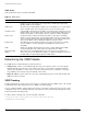
Figure 28 shows a simple VRRP network.
Figure 28: Simple VRRP network
In Figure 28, a virtual router is configured on Switch A and Switch B using these parameters:
• VRID is 1.
• MAC address is 00-00-5E-00-01-01.
• IP address is 192.168.1.3.
Switch A is configured with a priority of 255. This priority indicates that it is the master router. Switch B
is configured with a priority of 100. This indicates that it is a backup router.
The master router is responsible for forwarding packets sent to the virtual router. When the VRRP
network becomes active, the master router broadcasts an ARP request that contains the virtual router
MAC address (in this case, 00-00-5E-00-01-01) for each IP address associated with the virtual router.
Hosts on the network use the virtual router MAC address when they send traffic to the default gateway.
The virtual router IP address is configured to be the real interface address of the IP address owner. The
IP address owner is usually the master router. The virtual router IP address is also configured on each
backup router. However, in the case of the backup router, this IP address is not associated with a
EX_068
Switch A
Switch A = Master
VRID = 1
Virtual router IP address = 192.168.1.3
MAC address = 00-00-5E-00-01-01
Priority = 255
Default Gateway = 192.168.1.3
192.168.1.3
Switch B
Switch B = Backup
VRID = 1
Virtual router IP address = 192.168.1.3
MAC address = 00-00-5E-00-01-01
Priority = 100
192.168.1.5