
User's Guide
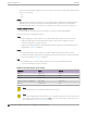
Table Of Contents
- Table of Contents
- Preface
- Welcome to Extreme Campus Controller
- Dashboard
- Monitor
- Sites List
- Device List
- Access Points List
- Smart RF Widgets
- Switches List
- Networks List
- Clients
- Policy
- Configure
- Network Configuration Steps
- Sites
- Add a Site
- Modifying Site Configuration
- Site Location
- Adding Device Groups to a Site
- Add or Edit a Configuration Profile
- Associated Profiles
- Associated Networks
- Mesh Point Profile Configuration
- Configure Client Bridge
- Understand Radio Mode
- Radio as a Sensor
- Advanced AP Radio Settings
- VLAN Profile Settings
- AirDefense Profile Settings
- ExtremeLocation Profile Settings
- IoT Profile Settings
- Positioning Profile Settings
- Analytics Profile Settings
- RTLS Settings
- Advanced Configuration Profile Settings
- Configuring RF Management
- Configuring a Floor Plan
- Advanced Tab
- Devices
- Networks
- Policy
- Automatic Adoption
- ExtremeGuest Integration
- AAA RADIUS Authentication
- Onboard
- Onboard AAA Authentication
- Manage Captive Portal
- Manage Access Control Groups
- Access Control Rules
- Tools
- Administration
- System Configuration
- Manage Administrator Accounts
- Extreme Campus Controller Applications
- Product License
- Glossary
- Index

Support for ExtremeWireless AP5xx Access Points
Extreme Campus Controller supports ExtremeWireless™ AP505i, AP510i/e, AP510i-1, AP560i/h/m/t/u
access points. These access points support more users and internet of things (IoT) devices. In addition
to both internal and external antennas, these APs support a Bluetooth Low Energy (BLE) antenna.
• AP510i/e indoor, one dual band 2.4GHz/5GHz radio and one 5GHz radio.
◦ Mode 1 — 2.4GHz service radio and 5GHz service radio
◦ Mode 2 — 2.4/5GHz Sensor and 5GHz service radio
◦ Mode 3 — 5GHz lower band service radio and 5GHz upper band service radio
◦ Radio Channels:
▪ Radio 1 can operate as:
• 2.4GHz with all 2.4GHz channels
• 5GHz lower band with 5GHz lower band channels (channels 36-64)
• 2.4/5GHz Sensor scanning and 2.4GHz and 5GHz channels
▪ Radio 2 can operate as
• 5GHz upper band with 5GHz upper band channels (channels above 100)
• 5GHz Full with 5GHz full channel list
Note
The AP510i-1 does not support IoT and the 5GHz radio does not support 160MHz
operation.
• AP505i indoor, one 2.4GHz radio and one 5GHz radio.
◦ Mode 1 — 2.4GHz service radio and 5GHz service radio. Can be used as a dedicated sensor.
• AP560i/h outdoor. The AP560i/h will follow the AP510 mode of operation depending on the power
source.
◦ Normal Mode
AP560 requires AT power (25W) to operate in normal mode with full performance. The AP must
be powered from one of the following scenarios:
▪ Ethernet port (GE1 PoE) connected to an AT switch port and Ethernet port (GE2) not
connected
▪ Ethernet port (GE2 PoE) connected to an AT switch port and Ethernet port (GE1) not
connected
▪ Both Ethernet port (GE1 PoE) and Ethernet port (GE2 PoE) connected to an AT switch port
▪ External power supply.
◦ Low Power Mode
When power source is AF (14.5W), the AP operates in Low Power mode with limited
performance. The AP560 operates in Low Power mode when GE1 or GE2 is connected to AF
switch port and no external power is connected. The following are AP560 Low Power Mode
limitations:
▪ MODE 1: dual band concurrent and MODE 2: sensor and 5GHz data forwarder:
• Radio 1 will be limited to 2x2 and max power 16dBm
• Radio 2 will be limited to 2x2 and max power 16dBm
Access Points List
Monitor
72 Extreme Campus Controller User Guide for version 5.46.03