
User's Guide
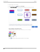


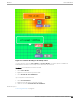
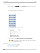
Table Of Contents
- Table of Contents
- Preface
- Welcome to Extreme Campus Controller
- Dashboard
- Monitor
- Sites List
- Device List
- Access Points List
- Smart RF Widgets
- Switches List
- Networks List
- Clients
- Policy
- Configure
- Network Configuration Steps
- Sites
- Add a Site
- Modifying Site Configuration
- Site Location
- Adding Device Groups to a Site
- Add or Edit a Configuration Profile
- Associated Profiles
- Associated Networks
- Mesh Point Profile Configuration
- Configure Client Bridge
- Understand Radio Mode
- Radio as a Sensor
- Advanced AP Radio Settings
- VLAN Profile Settings
- AirDefense Profile Settings
- ExtremeLocation Profile Settings
- IoT Profile Settings
- Positioning Profile Settings
- Analytics Profile Settings
- RTLS Settings
- Advanced Configuration Profile Settings
- Configuring RF Management
- Configuring a Floor Plan
- Advanced Tab
- Devices
- Networks
- Policy
- Automatic Adoption
- ExtremeGuest Integration
- AAA RADIUS Authentication
- Onboard
- Onboard AAA Authentication
- Manage Captive Portal
- Manage Access Control Groups
- Access Control Rules
- Tools
- Administration
- System Configuration
- Manage Administrator Accounts
- Extreme Campus Controller Applications
- Product License
- Glossary
- Index

Table 9: Device Status from the Floor Plans View (continued)
Status Description
Camera AP displayed as circular icon.
Extreme Defender Adapter
Ceiling-Mounted AP
Wall-Mounted AP
Use Auto Refresh to automatically refresh the information presented. From the Auto Refresh drop-
down field, select the refresh value. Valid values are:
• 30 Seconds
• 1 Minute
• 3 Minutes
• 5 Minutes
You can also select
to manually refresh the page anytime.
Both Associated and Unassociated clients are refreshed, provided they are marked as showing on the
Positioning dialog. For more information, see Positioning Heatmaps on page 60.
Related Topics
Device Context Menu on page 55
Filtering Floor Plan By Badge Information on page 55
Understanding Readiness Maps on page 57
User Interface Controls
The Floor Plan View oers user interface controls in a pane to the right of the map display.
• Floors. Click to display the floor maps associated with the selected device group. Double-click a
floor map in the right pane to display the full map.
• Maps. Click
to display a list of possible maps:
◦ Heatmap. Use heat maps to represent network connectivity based on one or more AP attributes.
◦ Channels. Show APs by channel.
◦ Link Speed. Device performance based on link speed.
◦ RFQI. Device performance based on radio frequency performance.
◦ BLE Coverage. Device performance based on BLE coverage. For a list of supported devices, see
Table 34 on page 149.
You can also select all APs or deselect all APs in one click.
• Positioning. Use heat maps to indicate Location Readiness and Foot trac.
Floor Plan View
Monitor
52 Extreme Campus Controller User Guide for version 5.46.03