
User's Guide
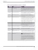
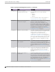

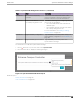

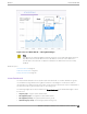

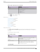
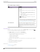
Table Of Contents
- Table of Contents
- Preface
- Welcome to Extreme Campus Controller
- Dashboard
- Monitor
- Sites List
- Device List
- Access Points List
- Smart RF Widgets
- Switches List
- Networks List
- Clients
- Policy
- Configure
- Network Configuration Steps
- Sites
- Add a Site
- Modifying Site Configuration
- Site Location
- Adding Device Groups to a Site
- Add or Edit a Configuration Profile
- Associated Profiles
- Associated Networks
- Mesh Point Profile Configuration
- Configure Client Bridge
- Understand Radio Mode
- Radio as a Sensor
- Advanced AP Radio Settings
- VLAN Profile Settings
- AirDefense Profile Settings
- ExtremeLocation Profile Settings
- IoT Profile Settings
- Positioning Profile Settings
- Analytics Profile Settings
- RTLS Settings
- Advanced Configuration Profile Settings
- Configuring RF Management
- Configuring a Floor Plan
- Advanced Tab
- Devices
- Networks
- Policy
- Automatic Adoption
- ExtremeGuest Integration
- AAA RADIUS Authentication
- Onboard
- Onboard AAA Authentication
- Manage Captive Portal
- Manage Access Control Groups
- Access Control Rules
- Tools
- Administration
- System Configuration
- Manage Administrator Accounts
- Extreme Campus Controller Applications
- Product License
- Glossary
- Index

Table 8: Radio Settings (continued)
Field Description
Channel Width Set the default channel width for the selected radio.
• 20 MHz
• 40 MHz
• 80 MHz (supported on 5GHz only 802.11ac and 802.11ax)
• 160 MHz
◦ AP5xx – Radio 1 and Radio 2 support 160 MHz
◦ AP3xx, AP4xx / AP4xxC – Radio 2 only (5 GHz band)
supports 160 MHz
◦ AP4000 – Radio 2 (5 GHz band) and Radio 3 (6 GHz
band) support 160 MHz
Note: AP xxx-1 access point models do not support 160
MHz on the 5 GHz radio.
A best practice is to use a predetermined width configured
as part of the design of the entire RF deployment. To learn
about how Smart RF handles channel width settings, see
Understanding Smart RF and Channel Width on page 166.
Auto Channel Select ACS optimizes channel arrangement based on the current
situation in the field if it is triggered on all APs in a deployment.
ACS only relies on the information observed at the time it is
triggered. After an AP has selected a channel, it remains
operating on that channel until the user changes the channel or
triggers ACS.
Floor Plan View
After the floor plan is configured, view the floor plan from Monitor > Sites. From the floor plan View.
you can view and filter information related to the placed devices.
Go to Monitor > Sites. Select a site and select the Floor Plans tab.
• View the following map information across the top of the screen:
◦ Map area, network coverage, environment, and scale.
◦ Number of ceiling mounted APs.
◦ Number of wall mounted APs.
◦ Number of devices in each status.
• Control which device badges appear on the map based on the selected device group or statistical
thresholds.
• View status, details, and statistics for each device.
• View clients associated with a selected device.
• View map zones for AP location.
Related Topics
Viewing a Floor Plan on page 51
Floor Plans on page 24
Floor Plan View
Monitor
50 Extreme Campus Controller User Guide for version 5.46.03