
User's Guide

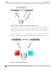
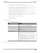
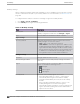
Table Of Contents
- Table of Contents
- Preface
- Welcome to Extreme Campus Controller
- Dashboard
- Monitor
- Sites List
- Device List
- Access Points List
- Smart RF Widgets
- Switches List
- Networks List
- Clients
- Policy
- Configure
- Network Configuration Steps
- Sites
- Add a Site
- Modifying Site Configuration
- Site Location
- Adding Device Groups to a Site
- Add or Edit a Configuration Profile
- Associated Profiles
- Associated Networks
- Mesh Point Profile Configuration
- Configure Client Bridge
- Understand Radio Mode
- Radio as a Sensor
- Advanced AP Radio Settings
- VLAN Profile Settings
- AirDefense Profile Settings
- ExtremeLocation Profile Settings
- IoT Profile Settings
- Positioning Profile Settings
- Analytics Profile Settings
- RTLS Settings
- Advanced Configuration Profile Settings
- Configuring RF Management
- Configuring a Floor Plan
- Advanced Tab
- Devices
- Networks
- Policy
- Automatic Adoption
- ExtremeGuest Integration
- AAA RADIUS Authentication
- Onboard
- Onboard AAA Authentication
- Manage Captive Portal
- Manage Access Control Groups
- Access Control Rules
- Tools
- Administration
- System Configuration
- Manage Administrator Accounts
- Extreme Campus Controller Applications
- Product License
- Glossary
- Index

The following is the trac flow of the topology illustrated in Figure 90:
• The AP establishes the active tunnel to connect to the primary Extreme Campus Controller.
• The Extreme Campus Controller sends the configuration to the AP. This configuration also contains
the port information of the backup Extreme Campus Controller.
• On the basis of the backup Extreme Campus Controller port information, the AP connects to the
backup Extreme Campus Controller via the backup tunnel.
• After the connection is established via the backup tunnel, the backup Extreme Campus Controller
sends the backup configuration to the wireless AP.
• The AP receives the backup configuration and stores it in its memory to use it for failing over to the
backup Extreme Campus Controller. During this entire time, the AP is connected to the primary
Extreme Campus Controller via the active tunnel.
Session availability applies only to the following topologies:
• Bridge Trac Locally at AC
• Bridge Trac Locally at AP
Availability Pair Settings
Table 92: Availability Pair Settings
Field Description
Peer IP Address Physical VLAN address of the paired appliance. This is the IP
address of the "Physical 1" interface (port esa0), which matches
the VLAN definition under System > Interfaces.
Role Select the role of the paired appliance. Valid values are Primary
or Backup.
Note: The configuration of the Primary appliance is copied to
the Secondary appliance.
Auto AP Balancing Select the load balancing configuration for the availability pair.
In an availability pair, an AP establishes an active tunnel to one
appliance and a backup tunnel to the other appliance. The
active tunnel is used to pass the client data over tunneled
topologies.
• In an Active-Active configuration, approximately half of the
APs establish an active tunnel to the primary appliance. The
remaining APs establish an active tunnel to the backup
appliance, spreading the load across the availability pair.
• In an Active-Passive configuration, all APs establish an
active tunnel to the primary appliance. The secondary
appliance is used for failover only.
Related Topics
Configuring VLANS on page 270
Administration
Availability
Extreme Campus Controller User Guide for version 5.46.03 369