
User's Guide

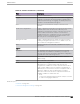
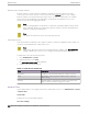
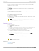

Table Of Contents
- Table of Contents
- Preface
- Welcome to Extreme Campus Controller
- Dashboard
- Monitor
- Sites List
- Device List
- Access Points List
- Smart RF Widgets
- Switches List
- Networks List
- Clients
- Policy
- Configure
- Network Configuration Steps
- Sites
- Add a Site
- Modifying Site Configuration
- Site Location
- Adding Device Groups to a Site
- Add or Edit a Configuration Profile
- Associated Profiles
- Associated Networks
- Mesh Point Profile Configuration
- Configure Client Bridge
- Understand Radio Mode
- Radio as a Sensor
- Advanced AP Radio Settings
- VLAN Profile Settings
- AirDefense Profile Settings
- ExtremeLocation Profile Settings
- IoT Profile Settings
- Positioning Profile Settings
- Analytics Profile Settings
- RTLS Settings
- Advanced Configuration Profile Settings
- Configuring RF Management
- Configuring a Floor Plan
- Advanced Tab
- Devices
- Networks
- Policy
- Automatic Adoption
- ExtremeGuest Integration
- AAA RADIUS Authentication
- Onboard
- Onboard AAA Authentication
- Manage Captive Portal
- Manage Access Control Groups
- Access Control Rules
- Tools
- Administration
- System Configuration
- Manage Administrator Accounts
- Extreme Campus Controller Applications
- Product License
- Glossary
- Index

Use the L2 Ports information to understand the OSI Layer 2 (Data Link Layer) physical topology of the
data plane. These ports represent the actual Ethernet Ports. LAG Ports are supported on physical
appliances only.
You can deploy Extreme Campus Controller in a redundant configuration, providing connectivity to two
dierent switch stacks for the same port function. Extreme Campus Controller supports configuration
attachment through a LAG to the same switch, or to two separate switches or stacks (MLAG).
• Static LAG supported.
• You can add a port to an existing LAG regardless of whether or not the port is in use. Assigned
VLANS are automatically remapped to the LAG port.
When LAG is disassembled, all LAG VLANs are automatically assigned to the first port member of
the LAG.
• In a High Availability pair, the LAG configuration automatically syncs to the peer appliance.
• Do not configure High Availability over a Bridged@AC L3 Interface.
Interfaces
Add network topologies. Topologies represent the networks with which the Extreme Campus Controller
and its APs interact. The attributes of a topology are: VLAN ID, Port, IP address, Mode, and certificates.
To add an interface, click Add.
Static Routes
Use static routes to set the default route of the Extreme Campus Controller so that device trac can be
forwarded to the default gateway. To add a static route, click Add.
Related Topics
Add an Interface on page 352
Add a Static Route on page 354
Add an Interface
You must be a system administrator to add a network interface. Take the following steps:
1. Go to Administration > System.
2. Under Interfaces click Add.
The Create New Interface dialog displays.
3. Configure the following parameters:
Table 89: Interface Parameters
Field Description
Name Name of the interface.
Mode Describes how trac is forwarded on the interface topology.
Options are:
• Physical - The topology is the native topology of a data
plane and it represents the actual Ethernet ports.
• Management - The native topology of the Extreme Campus
Controller management port.
Interfaces Administration
352 Extreme Campus Controller User Guide for version 5.46.03