
User's Guide
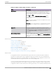
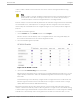
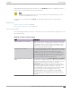
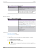
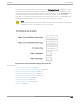
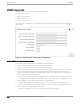
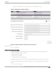
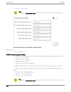
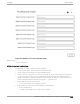
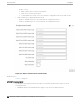
Table Of Contents
- Table of Contents
- Preface
- Welcome to Extreme Campus Controller
- Dashboard
- Monitor
- Sites List
- Device List
- Access Points List
- Smart RF Widgets
- Switches List
- Networks List
- Clients
- Policy
- Configure
- Network Configuration Steps
- Sites
- Add a Site
- Modifying Site Configuration
- Site Location
- Adding Device Groups to a Site
- Add or Edit a Configuration Profile
- Associated Profiles
- Associated Networks
- Mesh Point Profile Configuration
- Configure Client Bridge
- Understand Radio Mode
- Radio as a Sensor
- Advanced AP Radio Settings
- VLAN Profile Settings
- AirDefense Profile Settings
- ExtremeLocation Profile Settings
- IoT Profile Settings
- Positioning Profile Settings
- Analytics Profile Settings
- RTLS Settings
- Advanced Configuration Profile Settings
- Configuring RF Management
- Configuring a Floor Plan
- Advanced Tab
- Devices
- Networks
- Policy
- Automatic Adoption
- ExtremeGuest Integration
- AAA RADIUS Authentication
- Onboard
- Onboard AAA Authentication
- Manage Captive Portal
- Manage Access Control Groups
- Access Control Rules
- Tools
- Administration
- System Configuration
- Manage Administrator Accounts
- Extreme Campus Controller Applications
- Product License
- Glossary
- Index

AP305CX Professional Install
The antenna ports for the AP305CX are defined as follows:
• Radio 1 Port 2.4/5G-1
• Radio 1 Port 2.4/5G-2
• Radio 2 Port 5G-3
• Radio 2 Port 5G/IoT-4
The antenna list is dependent on your regulatory domain. The default antenna is the antenna with the
highest gain.
Figure 55: AP305CX External Antenna Configuration
AP310e/AP360e Professional Install Settings
The following rules apply to AP310e and AP360e antenna installation:
• Group 1 (2.4 GHz/5 GHz) accepts identical dual-band antennas.
• Group 2 (5 GHz) accepts identical 5 GHz or dual-band antennas.
• Antennas must be configured consecutively for each group. Group 1 starts with Port 1/Group 1 and
Group 2 starts with Port 3/Group 2. An equal number of antennas must be configured for both
groups. For example, to support a 2x2 deployment, install Group 1 and Group 2 — 2 antennas each.
• Mode 1. Radios 1 and 2 are enabled when:
◦ Both groups of antennas must be configured. Radio 1 is enabled only if one or more antennas are
configured in Group 1. Radio 2 is enabled only if one or more antennas are configured in Group 2.
• Mode 2. Radio 1 is a 2.4/5 GHz sensor and Radio 2 forwards trac.
◦ Radio 1 dual-band sensor is enabled only if one or more antennas are configured in Group 1.
◦ Radio 2 5 GHz WLAN service is enabled only if one or more antennas are configured in Group 2.
• Mode 3. Radios are configured Dual 5 GHz mode.
◦ Radio 1 is enabled only if one or more antennas are configured in Group 1.
Access Points
Configure
206 Extreme Campus Controller User Guide for version 5.46.03