
User's Guide
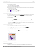
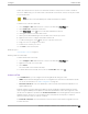
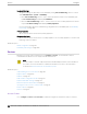
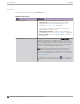
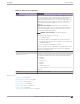
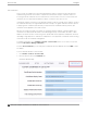
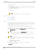
Table Of Contents
- Table of Contents
- Preface
- Welcome to Extreme Campus Controller
- Dashboard
- Monitor
- Sites List
- Device List
- Access Points List
- Smart RF Widgets
- Switches List
- Networks List
- Clients
- Policy
- Configure
- Network Configuration Steps
- Sites
- Add a Site
- Modifying Site Configuration
- Site Location
- Adding Device Groups to a Site
- Add or Edit a Configuration Profile
- Associated Profiles
- Associated Networks
- Mesh Point Profile Configuration
- Configure Client Bridge
- Understand Radio Mode
- Radio as a Sensor
- Advanced AP Radio Settings
- VLAN Profile Settings
- AirDefense Profile Settings
- ExtremeLocation Profile Settings
- IoT Profile Settings
- Positioning Profile Settings
- Analytics Profile Settings
- RTLS Settings
- Advanced Configuration Profile Settings
- Configuring RF Management
- Configuring a Floor Plan
- Advanced Tab
- Devices
- Networks
- Policy
- Automatic Adoption
- ExtremeGuest Integration
- AAA RADIUS Authentication
- Onboard
- Onboard AAA Authentication
- Manage Captive Portal
- Manage Access Control Groups
- Access Control Rules
- Tools
- Administration
- System Configuration
- Manage Administrator Accounts
- Extreme Campus Controller Applications
- Product License
- Glossary
- Index

Drawing Inner Walls
Wall materials aect the propagation of the signal and estimation models. An accurate representation
of the walls is essential to the accuracy of the model.
We recommend that you draw inner walls for a custom environment and choose material types, such as
concrete around stairwells. It is important that you draw inner walls that are made of concrete or brick
because these materials have a strong eect on the propagation. If installation requires that an AP be
placed within a walled area, then define both walls on either side of the AP.
Note
If you do not want to create a custom environment and draw the inner walls, you can select
basic inner wall types from the Environment drop-down list instead, such as oce drywalls or
cubicle walls. Oce drywall has minimal impact on the RF signal propagation.
To draw inner walls for a custom environment:
1. Go to Configure > Sites. Add a new site or select a site and select Floor Plans tab.
2. Select Draw Tools to display floor plan tools.
3. Select Custom from the Environment drop-down.
4. Under Draw Walls field, select a wall type.
The pen icon is enabled.
5. To anchor the line drawing, select a corner of the inner wall.
6. Select each corner of the inner wall to anchor the line, and progress to the next corner.
7. When you reach the end of your inner wall boundary, double-click the last corner to anchor the final
line and disable the pen tool.
Note
Right-click on a wall to change its type or to delete it. You can also select to modify a
wall or click to delete it.
Next, go to Placing Devices on page 181.
Placing Devices
As long as an AP is a member of a device group within the site, it can be placed on any map that is
associated with that site. From the floor plan Configuration, you must first select the device groups to
work with, then select a floor plan that includes APs from the selected device groups.
Switches associated with the site can be placed on a floor plan.
To place a device on a floor plan:
1. Go to Configure > Sites. Add a new site or select a site and select Floor Plans tab.
2. Select Draw Tools to display floor plan tools.
3. Select the Place Devices field, and select an AP or switch from the drop-down list. The Place
Devices field is populated with APs that are part of a selected device group and switches that are
part of the site.
This field supports auto-complete. You can type one or more characters in the Select a device to find
devices.
Configure
Configuring a Floor Plan
Extreme Campus Controller User Guide for version 5.46.03 181