
User's Guide
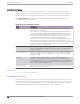

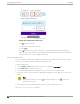
Table Of Contents
- Table of Contents
- Preface
- Welcome to Extreme Campus Controller
- Dashboard
- Monitor
- Sites List
- Device List
- Access Points List
- Smart RF Widgets
- Switches List
- Networks List
- Clients
- Policy
- Configure
- Network Configuration Steps
- Sites
- Add a Site
- Modifying Site Configuration
- Site Location
- Adding Device Groups to a Site
- Add or Edit a Configuration Profile
- Associated Profiles
- Associated Networks
- Mesh Point Profile Configuration
- Configure Client Bridge
- Understand Radio Mode
- Radio as a Sensor
- Advanced AP Radio Settings
- VLAN Profile Settings
- AirDefense Profile Settings
- ExtremeLocation Profile Settings
- IoT Profile Settings
- Positioning Profile Settings
- Analytics Profile Settings
- RTLS Settings
- Advanced Configuration Profile Settings
- Configuring RF Management
- Configuring a Floor Plan
- Advanced Tab
- Devices
- Networks
- Policy
- Automatic Adoption
- ExtremeGuest Integration
- AAA RADIUS Authentication
- Onboard
- Onboard AAA Authentication
- Manage Captive Portal
- Manage Access Control Groups
- Access Control Rules
- Tools
- Administration
- System Configuration
- Manage Administrator Accounts
- Extreme Campus Controller Applications
- Product License
- Glossary
- Index

Figure 50: Setting Floor Plan Scale
• Click to draw a doorway.
a. Draw a line to represent a doorway.
b. Click Apply.
• Click to draw the floor length. Draw a line on the map that represents an actual physical
distance. On the map, double-click the beginning and ending points of the line. The length of the
wall (based on the set scale) is displayed on the map.
Drawing Boundary Walls
Draw the outside boundary of the building. The area within the boundary is used to determine device
location and coverage. The area outside the boundary is ignored.
To draw boundary lines:
1. Go to Configure > Sites. Add a new site or select a site and select Floor Plans tab.
2. Select Draw Tools to display floor plan tools.
3. To anchor the beginning of the boundary line, click a corner of the outside boundary.
4. Click each corner to anchor the line. The drawing line zigzags across the image as you anchor each
corner.
Note
If you make a mistake, you can click to edit the boundary or click to delete the
boundary and start over.
5. When you finish the boundary, double-click the last corner to disable the pen tool.
Next, go to Drawing Inner Walls on page 181.
Configuring
a Floor Plan Configure
180 Extreme Campus Controller User Guide for version 5.46.03