
User's Guide
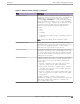
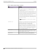
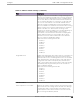


Table Of Contents
- Table of Contents
- Preface
- Welcome to Extreme Campus Controller
- Dashboard
- Monitor
- Sites List
- Device List
- Access Points List
- Smart RF Widgets
- Switches List
- Networks List
- Clients
- Policy
- Configure
- Network Configuration Steps
- Sites
- Add a Site
- Modifying Site Configuration
- Site Location
- Adding Device Groups to a Site
- Add or Edit a Configuration Profile
- Associated Profiles
- Associated Networks
- Mesh Point Profile Configuration
- Configure Client Bridge
- Understand Radio Mode
- Radio as a Sensor
- Advanced AP Radio Settings
- VLAN Profile Settings
- AirDefense Profile Settings
- ExtremeLocation Profile Settings
- IoT Profile Settings
- Positioning Profile Settings
- Analytics Profile Settings
- RTLS Settings
- Advanced Configuration Profile Settings
- Configuring RF Management
- Configuring a Floor Plan
- Advanced Tab
- Devices
- Networks
- Policy
- Automatic Adoption
- ExtremeGuest Integration
- AAA RADIUS Authentication
- Onboard
- Onboard AAA Authentication
- Manage Captive Portal
- Manage Access Control Groups
- Access Control Rules
- Tools
- Administration
- System Configuration
- Manage Administrator Accounts
- Extreme Campus Controller Applications
- Product License
- Glossary
- Index

AirDefense Profile Settings
The AP integrates with the Extreme AirDefense (AirDefense), oering an additional profile option that
allows the AP to function as an AirDefense sensor or to act as a sensor and retain the ability to forward
trac.
When the AP is configured with an AirDefense dedicated sensor profile, the functionality of the AP is
controlled by the AirDefense server. When the AP is configured as a AirDefense Radio Share profile, it
continues to forward trac while sending packets to an AirDefense server. To ensure rate performance,
an AP configured with a Radio Share profile does not forward its own Tx/Rx data to the ADSP server.
The AP3xx, AP4xx, and AP5xx support Radio Share and OCS. You have the option to scan neighboring
channels in addition to the operating channel. AP4xx also oers a separate sensor radio.
1. Configure the following settings:
Table 32: AirDefense Profile Settings
Field Description
Name Name of AirDefense profile.
Add Server Address The IP address of the AirDefense servers. Provide the FQDN or IPv4
string, maximum 255 characters.
Enter the IP address, then click . The IP address is added to the
Servers list.
Note: When using the AirDefense Base (add-on container
application), provide the IP address of the Extreme Campus
Controller data port that is reachable by the APs and sensors.
Port Specify a port for the AirDefense server. The default port is 443
(used with a dedicated external AirDefense Server).
Note: When using the AirDefense Base (add-on container
application), configure port number to 32032.
Servers
List of IP addresses for servers. Click to remove an IP address
from the list.
2. Select Save.
Related Topics
Radio as a Sensor on page 138
Advanced AP Radio Settings on page 139
Add or Edit a Configuration Profile on page 122
ADSP Support on .11ax APs on page 147
AirDefense Base Application on page 389
ADSP Support on .11ax APs
The following ADSP features are supported on the AP3xx, AP4xx, and AP5xx:
• LiveView under Sensor Mode
• LiveView under Radio Share Mode
• Scan Pattern Support from the ADSP Server for Sensor.
Configure
Add or Edit a Configuration Profile
Extreme Campus Controller User Guide for version 5.46.03 147