User's Guide 99 Washington Street Melrose, MA 02176 Phone 781-665-1400 Toll Free 1-800-517-8431 Visit us at www.TestEquipmentDepot.
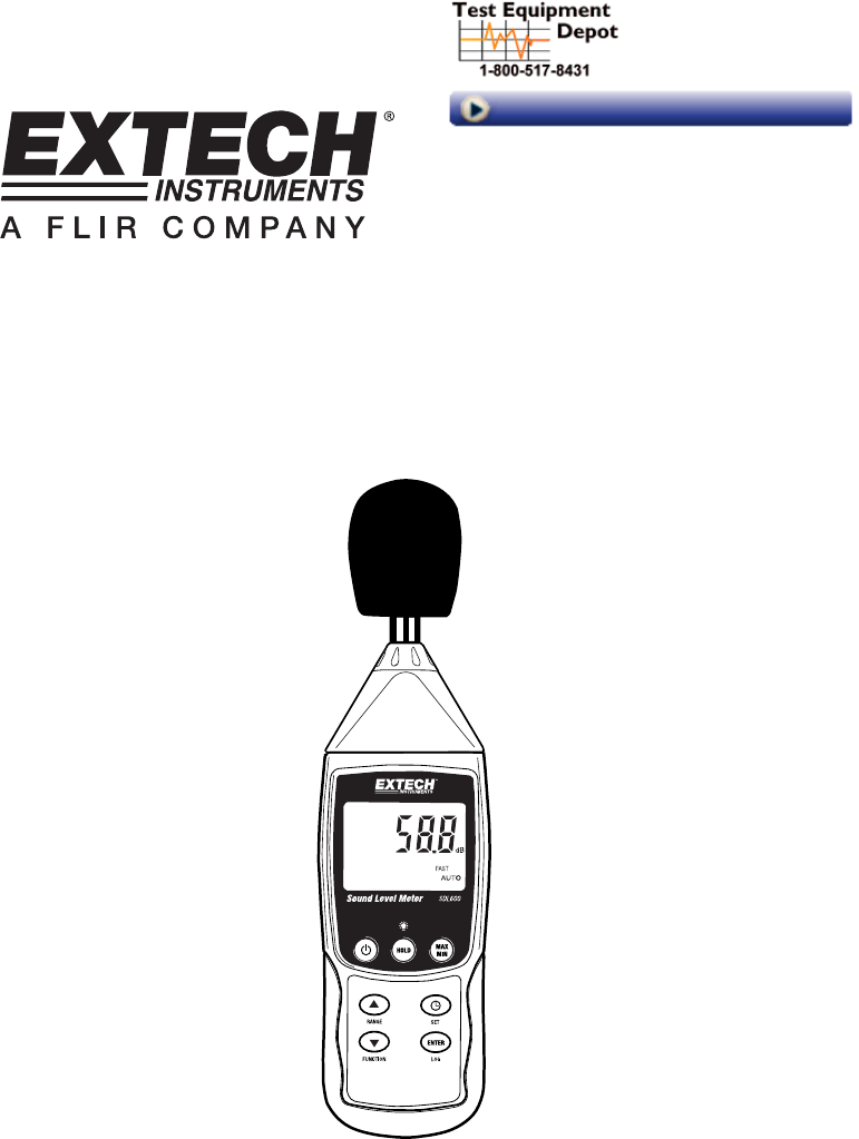
Introduction Congratulations on your purchase of the Extech SDL600 Sound Level Meter. This meter displays and stores sound level readings in the 30 to 130 db range. The SDL600meets ANSI and IEC 61672 class 2 standards and includes ‘A’ and ‘C’ frequency weighting and FAST and SLOW response time. Logged data readings are stored on an SD card for transfer to a PC. This meter is shipped fully tested and calibrated and, with proper use, will provide years of reliable service.
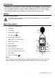
Getting Started Accessories • The SDL600 includes batteries, SD card, windscreen, and carry case. If items are missing please contact the distributor through which this product was purchased • An optional AC adaptor is available through Extech distributors • Optional sound level calibrators are available through Extech distributors. Calibrators are highly recommended for best accuracy and repeatability. Power ON-OFF for at least 1.5 seconds to power ON the meter.
Frequency Weighting ‘A’ and ‘C’ Select ‘A’ or ‘C’ frequency weighting in the SETUP Mode. With ‘A’ weighting selected, the frequency response of the meter is similar to the response of the human ear. ‘A’ weighting is commonly used for environmental or hearing conservation programs such as OSHA regulatory testing and noise ordinance law enforcement. ‘C’ weighting is a much flatter response and is suitable for the sound level analysis of machines, engines, etc.
Setup Mode Basic settings at a glance To view the current configuration of the meter with regard to time, date, and datalogging sampling rate press the SET button momentarily. The meter will now display the configuration in quick succession. Repeat as necessary to observe all of the information. Accessing the Setup mode 1. Press and hold the SET button for at least 1.5 seconds to access the Setup menu. 2. Press the SET button momentarily to step through the available parameters.
Enabling/Disabling the Auto Power OFF Feature 1. 2. 3. 4. Access the PoFF parameter. Use the arrow buttons to select ON (enable) or OFF (disable). With the Auto Power OFF feature enabled, the meter will automatically switch OFF after 5 minutes of inactivity. Press ENTER to confirm setting. Press and hold the SET button for at least 1.5 seconds to exit to the normal operation mode (or simply wait 7 seconds for the meter to automatically switch to the normal operating mode).
Datalogging and PC Interface Types of Data Recording • • Manual Datalogging: Manually log up to 99 readings onto an SD card via push-button press. Automatic Datalogging: Automatically log data onto an SD memory card where the number of data points is virtually limited only by the card size. Readings are logged at a rate specified by the user. SD Card Information • • • Insert an SD card (from 1G size up to 16G) into the SD card slot at the bottom of the meter.
Automatic Datalogging In automatic datalogging mode the meter takes and stores a reading at a user-specified sampling rate onto an SD memory card. The meter defaults to a sampling rate of one second. To change the sampling rate, refer to the Setup Mode section (the sampling rate cannot be ‘0’ for automatic datalogging): 1. Select the sampling rate in the Setup Mode (refer to Setup Mode section) to a value other than zero. 2. Press and hold the LOG button for at least 1.5 seconds.
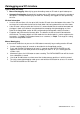
Spreadsheet data example RS-232/USB PC Interface The optional 407001A software kit (software and cable) allows streaming of data to a PC via the RS232 Output jack. AC Power Adaptor This meter is normally powered by six (6) 1.5V ‘AA’ batteries. An optional 9V power adaptor is available. When the adaptor is used, the meter is permanently powered and the power button will be disabled. 9 SDL600-EU-EN-V1.
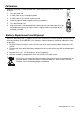
Calibration Frequent calibration is recommended and is often required by noise standards and directives. 1. Turn the meter ON 2. Put the meter in the ‘A’ weighting mode 3. Put the meter in the ‘SLOW’ response mode 4. Place the optional 94db calibrator onto the microphone 5. Turn the calibrator ON 6. Adjust the meter’s CAL potentiometer (located on the right side under the snapoff compartment cover) so that the meter’s display matches the output of the calibrator (94.
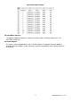
Specifications General Specifications Display Status indicators Microphone Measurement Units Measurement ranges Frequency range Frequency weighting Time Response Calibration Datalogger Sampling Rate Memory Card Display update rate Data Output AC Output 52 x 38mm (2 x 1.5”) Backlit LCD Out-of-range (----) and low battery 12.7mm (0.5”) electret condenser microphone Decibels Automatic and Manual (30 to 80, 50 to 100, and 80 to 130dB) 31.